Lexus NX: Reverse Signal Circuit
DESCRIPTION
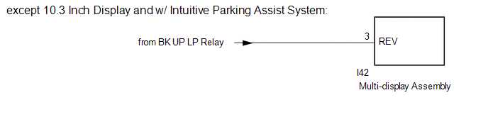
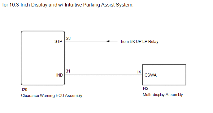
The multi-display receives a reverse signal from the BK UP LP relay*1 or clearance warning ECU assembly*2.
*1: except 10.3 Inch Display and w/ Intuitive Parking Assist System
*2: for 10.3 Inch Display and w/ Intuitive Parking Assist System
WIRING DIAGRAM
CAUTION / NOTICE / HINT
NOTICE:
-
When "!" mark is displayed on the multi-display assembly after disconnecting the cable from the negative (-) auxiliary battery terminal, correct the steering angle neutral point.
Click here
.gif)
-
Depending on the parts that are replaced or operations that are performed during vehicle inspection or maintenance, calibration of other systems as well as the parking assist monitor system may be needed.
Click here
PROCEDURE
| 1. | CHECK BACK-UP LIGHT |
(a) Check that the back-up light comes on.
OK:
The back-up light comes on.
| Result | Proceed to |
|---|---|
| OK (except 10.3 Inch Display and w/ Intuitive Parking Assist System) | A |
| OK (for 10.3 Inch Display and w/ Intuitive Parking Assist System) | B |
| NG | C |
| B | .gif) | GO TO STEP 3 |
| C | | GO TO LIGHTING SYSTEM (EXT) |
|
.gif)
| 2. | CHECK HARNESS AND CONNECTOR (REVERSE SIGNAL) |
| (a) Disconnect the multi-display assembly connector. |
|
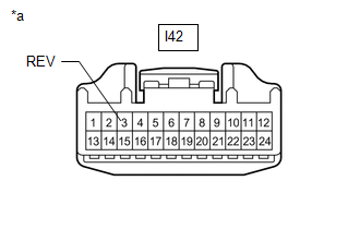
(b) Measure the voltage according to the value(s) in the table below.
Standard Voltage:
| Tester Connection | Condition | Specified Condition |
|---|---|---|
| I42-3 (REV) - Body ground | Power switch on (IG) Shift position in R | 11 to 14 V |
| I42-3 (REV) - Body ground | Power switch on (IG) Shift position not in R | Below 1 V |
| OK | | PROCEED TO NEXT SUSPECTED AREA SHOWN IN PROBLEM SYMPTOMS TABLE |
| NG | | REPAIR OR REPLACE HARNESS OR CONNECTOR |
| 3. | CHECK HARNESS AND CONNECTOR (REVERSE SIGNAL) |
| (a) Disconnect the clearance warning ECU assembly connector. |
|
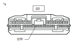
(b) Measure the voltage according to the value(s) in the table below.
Standard Voltage:
| Tester Connection | Condition | Specified Condition |
|---|---|---|
| I20-28 (STP) - Body ground | Power switch on (IG) Shift position in R | 11 to 14 V |
| I20-28 (STP) - Body ground | Power switch on (IG) Shift position not in R | Below 1 V |
| NG | | REPAIR OR REPLACE HARNESS OR CONNECTOR |
|
| 4. | CHECK HARNESS AND CONNECTOR (CLEARANCE WARNING ECU ASSEMBLY - MULTI-DISPLAY ASSEMBLY) |
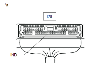
(a) Disconnect the I20 clearance warning ECU assembly connector.
(b) Disconnect the I42 multi-display assembly connector.
(c) Measure the resistance according to the value(s) in the table below.
Standard Voltage:
| Tester Connection | Condition | Specified Condition |
|---|---|---|
| I20-31 (IND) - I42-14 (CSWA) | Always | Below 1 Ω |
| I20-31 (IND) or I42-14 (CSWA) - Body ground | Always | 10 kΩ or higher |
| NG | | REPAIR OR REPLACE HARNESS OR CONNECTOR |
|
| 5. | INSPECT CLEARANCE WARNING ECU ASSEMBLY |
| (a) Disconnect the multi-display assembly connector. |
|
(b) Measure the voltage according to the value(s) in the table below.
Standard Voltage:
| Tester Connection | Condition | Specified Condition |
|---|---|---|
| I20-31 (IND) - Body ground | Power switch on (IG) Shift position in R | Below 3 V |
| I20-31 (IND) - Body ground | Power switch on (IG) Shift position not in R | 8 V or higher |
| OK | | PROCEED TO NEXT SUSPECTED AREA SHOWN IN PROBLEM SYMPTOMS TABLE |
| NG | | REPLACE CLEARANCE WARNING ECU ASSEMBLY |
READ NEXT:
 Image from Camera for Parking Assist Monitor is Abnormal
DESCRIPTION The video signal from the rear television camera assembly is transmitted to the multi-display assembly. WIRING DIAGRAM CAUTION / NOTICE / HINT NOTICE:
When the "!" mark is displayed on
Components
COMPONENTS ILLUSTRATION *1 BLIND SPOT MONITOR BUZZER *2 DECK TRIM SIDE PANEL ASSEMBLY RH *3 LUGGAGE HOLD BELT STRIKER ASSEMBLY *4 NO. 1 LUGGAGE COMPARTMENT TRIM HOOK *5 REAR
SEE MORE:
Installation
INSTALLATION PROCEDURE 1. INSTALL WINDSHIELD WIPER RELAY ASSEMBLY (a) Attach the 2 claws to install the windshield wiper relay assembly. 2. INSTALL ECU INTEGRATION BOX RH Click here 3. INSTALL NO. 2 INSTRUMENT PANEL UNDER COVER SUB-ASSEMBLY Click here 4. INSTALL GLOVE COMPARTMENT DOOR ASSEMBLY C
Seat Belt Tension Reducer System
Parts LocationPARTS LOCATION ILLUSTRATION *A w/ Memory - - *1 FRONT SEAT INNER BELT ASSEMBLY RH *2 FRONT SEAT INNER BELT ASSEMBLY LH *3 FRONT SEAT OUTER BELT ASSEMBLY RH *4 FRONT SEAT OUTER BELT ASSEMBLY LH *5 FRONT POWER SEAT SWITCH LH *6 INSTRUMENT PANEL JU
