Lexus NX: Components
Lexus NX Service Manual / Vehicle Interior / Seat Belt / Seat Belt Warning Light (for Rear Side) / Components
COMPONENTS
ILLUSTRATION
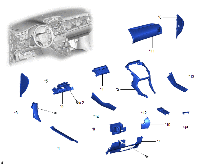
| *1 | AIR CONDITIONING CONTROL ASSEMBLY (SEAT BELT WARNING LIGHT) | *2 | CENTER INSTRUMENT CLUSTER FINISH PANEL ASSEMBLY |
| *3 | COWL SIDE TRIM BOARD LH | *4 | DOOR SCUFF PLATE ASSEMBLY LH |
| *5 | INSTRUMENT SIDE PANEL LH | *6 | INSTRUMENT SIDE PANEL RH |
| *7 | LOWER NO. 1 INSTRUMENT PANEL FINISH PANEL | *8 | NO. 1 INSTRUMENT PANEL SAFETY PAD SUB-ASSEMBLY |
| *9 | NO. 1 INSTRUMENT PANEL UNDER COVER SUB-ASSEMBLY | *10 | NO. 1 SWITCH HOLE BASE |
| *11 | NO. 2 INSTRUMENT PANEL SAFETY PAD SUB-ASSEMBLY | *12 | REAR CONSOLE ARMREST ASSEMBLY |
| *13 | UPPER NO. 1 CONSOLE PANEL GARNISH | *14 | UPPER NO. 2 CONSOLE PANEL GARNISH |
| *15 | UPPER REAR CONSOLE PANEL | - | - |
READ NEXT:
 Removal
REMOVAL PROCEDURE 1. REMOVE MULTI-DISPLAY ASSEMBLY Click here 2. REMOVE DOOR SCUFF PLATE ASSEMBLY LH Click here 3. REMOVE COWL SIDE TRIM BOARD LH Click here 4. REMOVE REAR CONSOLE ARMREST ASS
Inspection
INSPECTION PROCEDURE 1. INSPECT AIR CONDITIONING CONTROL ASSEMBLY (SEAT BELT WARNING LIGHT) (for Rear Side) (a) Check the seat belt warning light illumination. OK: Measurement Condition Speci
Installation
INSTALLATION PROCEDURE 1. INSTALL AIR CONDITIONING CONTROL ASSEMBLY (SEAT BELT WARNING LIGHT) (a) Connect the 2 connectors. (b) Attach the 6 clips to install the air conditioning control assembly (
SEE MORE:
How To Proceed With Troubleshooting
CAUTION / NOTICE / HINT HINT:
The power back door system troubleshooting procedure is based on the premise that the smart access system with push-button start (for Entry Function) is operating normally. Check the smart access system with push-button start (for Entry Function) first before trouble
System Description
SYSTEM DESCRIPTION POWER MIRROR CONTROL SYSTEM DESCRIPTION (a) This system has the following functions: power retract function, auto power retract function, electrical remote control function, reverse shift-linked function, memory function, automatic glare-resistant EC mirror function and mirror hea
© 2016-2026 Copyright www.lexunx.com
