.gif)
- Power switch off
- Electrical key transmitter sub-assembly not inside vehicle
- Within 30 seconds of closing any door using the door outside handle
Lexus NX: Room Oscillator does not Recognize Key
Lexus NX Service Manual / Vehicle Interior / Theft Deterrent / Keyless Entry / Smart Access System With Push-button Start (for Entry Function) / Room Oscillator does not Recognize Key
DESCRIPTION
If code verification cannot be performed in the vehicle interior, there may be problems with the communication between the vehicle (No. 1 indoor electrical key antenna assembly (front floor), No. 2 indoor electrical key antenna assembly (rear floor) or No. 3 indoor electrical key antenna assembly (inside luggage)) and electrical key transmitter sub-assembly, or the certification ECU (smart key ECU assembly) may be malfunctioning. When the electrical key transmitter sub-assembly is brought into the vehicle, verification of the key ID code transmitted from the electrical key transmitter sub-assembly and the key ID code stored in the certification ECU (smart key ECU assembly) is performed. If verification cannot be performed or the codes do not match, the power switch cannot be turned on (IG) and the hybrid control system cannot be started.
When a door is unlocked and the electrical key transmitter sub-assembly is brought into the vehicle, the certification ECU (smart key ECU assembly) activates the indoor electrical key antenna assembly which transmits radio waves to detect the electrical key transmitter sub-assembly. If the electrical key transmitter sub-assembly recognizes that it is in the detection area, it responds with the key ID code. This information is received by the indoor electrical key antenna and then sent to the certification ECU (smart key ECU assembly).
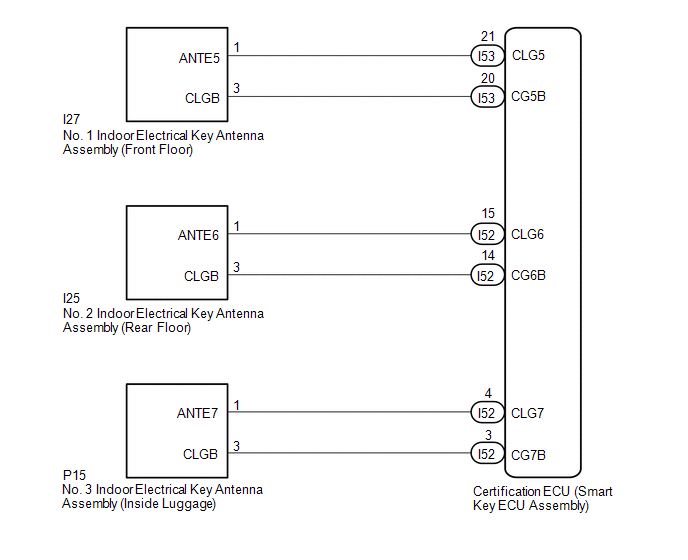
WIRING DIAGRAM
CAUTION / NOTICE / HINT
NOTICE:
-
The smart access system with push-button start (for Entry Function) uses the LIN communication system and CAN communication system. Inspect the communication function by following How to Proceed with Troubleshooting. Troubleshoot the smart access system with push-button start (for Entry Function) after confirming that the communication systems are functioning properly.
Click here
.gif)
- When using the Techstream with the power switch off, connect the Techstream to the DLC3 and turn a courtesy light switch on and off at intervals of 1.5 seconds or less until communication between the Techstream and the vehicle begins. Then select the vehicle type under manual mode and enter the following menus: Body Electrical / Smart Access. While using the Techstream, periodically turn a courtesy light switch on and off at intervals of 1.5 seconds or less to maintain communication between the Techstream and the vehicle.
-
Before replacing the certification ECU (smart key ECU assembly), refer to smart access system with push-button start (for Entry Function) Precaution.
Click here
- After repair, confirm that no DTCs are output by performing "DTC Output Confirmation Operation".
- The indoor electrical key antenna assemblies have an antenna coil between each terminal.
- The door control receiver assembly is also related to interior verification.
PROCEDURE
| 1. | CHECK START OPERATION |
(a) Using another registered electrical key transmitter sub-assembly, check that the hybrid control system starts.
| Result | Proceed to |
|---|---|
| Hybrid control system can be started | A |
| Hybrid control system cannot be started | B |
| A | .gif) | END (ELECTRICAL KEY TRANSMITTER SUB-ASSEMBLY WAS DEFECTIVE) |
|
| 2. | CHECK ENTRY LOCK OPERATION |
(a) Check that the entry lock and unlock functions operate on each door.
Click here
HINT:
If the door control receiver is defective, code verification does not begin in the cabin and the entry lock and unlock functions do not operate.
| Result | Proceed to |
|---|---|
| All door entry functions operate normally (w/ Wireless Charging System) | A |
| All door entry functions operate normally (w/o Wireless Charging System) | B |
| All door entry functions does not operate normally | C |
| B | | GO TO STEP 4 |
| C | | GO TO OTHER PROBLEM |
|
| 3. | CHECK WIRELESS CHARGING SYSTEM |
(a) Wireless charging system off.
Click here
(b) Check that interior certification is performed.
Click here
| Result | Proceed to |
|---|---|
| Operate normally | A |
| Not operate normally | B |
| B | | GO TO WIRELESS CHARGING SYSTEM |
|
| 4. | CHECK PUSH-BUTTON START FUNCTION |
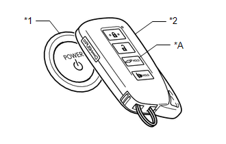
(a) Remove the transmitter battery of the electrical key transmitter sub-assembly.
Click here
| (b) With the brake pedal depressed, face the logo side of the electrical key transmitter sub-assembly towards the power switch, hold the transmitter near the power switch and then press the power switch. |
|
(c) When operating the power switch, check whether the hybrid control system starts.
HINT:
- When the electrical key transmitter sub-assembly cannot be verified even though it is inside the detection area, the hybrid control system start check can be performed by removing the transmitter battery from the electrical key transmitter sub-assembly and holding the electrical key transmitter sub-assembly near the power switch.
- If the hybrid control system cannot be started when performing this inspection, the certification ECU (smart key ECU assembly) or steering lock ECU (steering lock actuator assembly) may be malfunctioning.
| Result | Proceed to |
|---|---|
| Hybrid control system can be started | A |
| Hybrid control system cannot be started | B |
| B | | GO TO SMART ACCESS SYSTEM WITH PUSH-BUTTON START (FOR START FUNCTION) |
|
| 5. | CHECK WAVE ENVIRONMENT |
(a) Install the transmitter battery to the electrical key transmitter sub-assembly.
Click here
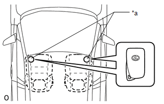
(b) Bring the electrical key transmitter sub-assembly near the No. 1 indoor electrical key antenna assembly (front floor) and perform a smart access system with push-button start check.
Click here
NOTICE:
Communication may not be possible if the electrical key transmitter sub-assembly is within 0.2 m (0.656 ft.) of the No. 1 indoor electrical key antenna assembly (front floor).
Click here
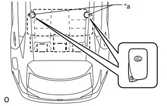
(c) Bring the electrical key transmitter sub-assembly near the No. 2 indoor electrical key antenna assembly (rear floor) and perform a smart access system with push-button start check.
Click here
HINT:
Check that the customize status of the "Ignition Available Area" has been "All".
Click here
NOTICE:
Communication may not be possible if the electrical key transmitter sub-assembly is within 0.2 m (0.656 ft.) of the center of the No. 2 indoor electrical key antenna assembly (rear floor).
Click here
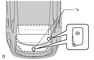
(d) Bring the electrical key transmitter sub-assembly near the No. 3 indoor electrical key antenna assembly (inside luggage) and perform a smart access system with push-button start check.
Click here
HINT:
Check that the customize status of the "Ignition Available Area" has been "All".
Click here
NOTICE:
Communication may not be possible if the electrical key transmitter sub-assembly is within 0.2 m (0.656 ft.) of the center of the No. 3 indoor electrical key antenna assembly (inside luggage).
Click here
HINT:
- As the effect of wave interference decreases by moving the electrical key transmitter sub-assembly close to each indoor electrical key antenna assembly, it may be possible to check whether wave interference is the cause of the problem.
- If the inspection result is that the problem only occurs in certain locations or at certain times of day, the possibility of wave interference is high. Also, added vehicle components may cause wave interference. If installed, remove them and perform the operation check.
- There may be wave interference if the vehicle is near broadcasting antennas, large video displays, wireless garage door opener systems, wireless security cameras, home security systems, etc. In this case, move the vehicle to a different location and check if there is any improvement.
- If a tool for checking radio waves, such as a signal strength meter, is available, move around the area while observing both the LF band (used by the vehicle antenna to form the detection area) and RF band (used by the electrical key transmitter sub-assembly for transmission) to check for locations where there is wave interference.
OK:
The hybrid control system starts when the electrical key transmitter sub-assembly is held near each indoor electrical key antenna assembly and the power switch is pressed.
| OK | | AFFECTED BY WAVE INTERFERENCE |
|
| 6. | CHECK FOR DTC |
(a) Check for DTCs.
Body Electrical > Smart Access > Trouble CodesOK:
DTCs are not output.
| NG | | GO TO DIAGNOSTIC TROUBLE CODE CHART |
|
| 7. | CHECK KEY DIAGNOSTIC MODE |
(a) Check the following antennas in key diagnostic mode.
Body Electrical > Smart Access > Utility| Tester Display |
|---|
| Communication Check(Key Diag Mode) |
(b) Select either channel 1 or channel 2 and inspect key diagnostic mode for each channel.
| (1) Check the No. 1 indoor electrical key antenna assembly (front floor): When the electrical key transmitter sub-assembly is at either inspection point, check that the wireless buzzer sounds. HINT:
|
|
| (2) Check the No. 2 indoor electrical key antenna assembly (rear floor): When the electrical key transmitter sub-assembly is at either inspection point, check that the wireless buzzer sounds. HINT:
|
|
| (3) Check the No. 3 indoor electrical key antenna assembly (inside luggage): When the electrical key transmitter sub-assembly is at either inspection point, check that the wireless buzzer sounds. HINT:
|
|
| Result | Proceed to |
|---|---|
| The wireless buzzer sounds/does not sound for all indoor electrical key antenna assemblies | A |
| The wireless buzzer does not sound for only the No. 1 indoor electrical key antenna assembly (front floor) | B |
| The wireless buzzer does not sound for only the No. 2 indoor electrical key antenna assembly (rear floor) | C |
| The wireless buzzer does not sound for only the No. 3 indoor electrical key antenna assembly (inside luggage) | D |
| A | | REPLACE CERTIFICATION ECU (SMART KEY ECU ASSEMBLY) |
| C | | GO TO STEP 12 |
| D | | GO TO STEP 16 |
|
| 8. | CHECK HARNESS AND CONNECTOR (CERTIFICATION ECU (SMART KEY ECU ASSEMBLY) - NO. 1 INDOOR ELECTRICAL KEY ANTENNA ASSEMBLY (FRONT FLOOR)) |
(a) Disconnect the I53 certification ECU (smart key ECU assembly) connector.
(b) Disconnect the I27 No. 1 indoor electrical key antenna assembly (front floor) connector.
(c) Measure the resistance according to the value(s) in the table below.
Standard Resistance:
| Tester Connection | Condition | Specified Condition |
|---|---|---|
| I53-21 (CLG5) - I27-1 (ANTE5) | Always | Below 1 Ω |
| I53-20 (CG5B) - I27-3 (CLGB) | Always | Below 1 Ω |
| I53-21 (CLG5) or I27-1 (ANTE5) - Body ground | Always | 10 kΩ or higher |
| I53-20 (CG5B) or I27-3 (CLGB) - Body ground | Always | 10 kΩ or higher |
(d) Reconnect the I53 certification ECU (smart key ECU assembly) connector.
| NG | | REPAIR OR REPLACE HARNESS OR CONNECTOR |
|
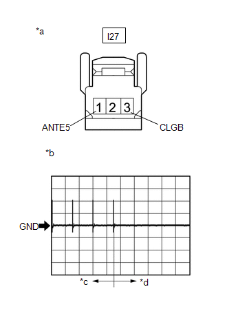
| 9. | CHECK CERTIFICATION ECU (SMART KEY ECU ASSEMBLY) (OUTPUT TO NO. 1 INDOOR ELECTRICAL KEY ANTENNA ASSEMBLY (FRONT FLOOR)) |
| (a) Using an oscilloscope, check the waveform. OK:
|
|
| NG | | REPLACE CERTIFICATION ECU (SMART KEY ECU ASSEMBLY) |
|
| 10. | REPLACE NO. 1 INDOOR ELECTRICAL KEY ANTENNA ASSEMBLY (FRONT FLOOR) |
(a) Temporarily replace the No. 1 indoor electrical key antenna assembly (front floor) with a new one.
Click here
|
| 11. | CHECK KEY DIAGNOSTIC MODE |
(a) Check the following antenna in key diagnostic mode.
Body Electrical > Smart Access > Utility| Tester Display |
|---|
| Communication Check(Key Diag Mode) |
(b) Select either channel 1 or channel 2 and inspect key diagnostic mode for each channel.
| (1) Check the No. 1 indoor electrical key antenna assembly (front floor): When the electrical key transmitter sub-assembly is at either inspection point, check that the wireless buzzer sounds. HINT:
OK: Wireless buzzer sounds. |
|
| OK | | END (NO. 1 INDOOR ELECTRICAL KEY ANTENNA ASSEMBLY (FRONT FLOOR) WAS DEFECTIVE) |
| NG | | REPLACE CERTIFICATION ECU (SMART KEY ECU ASSEMBLY) |
| 12. | CHECK HARNESS AND CONNECTOR (CERTIFICATION ECU (SMART KEY ECU ASSEMBLY) - NO. 2 INDOOR ELECTRICAL KEY ANTENNA ASSEMBLY (REAR FLOOR)) |
(a) Disconnect the I52 certification ECU (smart key ECU assembly) connector.
(b) Disconnect the I25 No. 2 indoor electrical key antenna assembly (rear floor) connector.
(c) Measure the resistance according to the value(s) in the table below.
Standard Resistance:
| Tester Connection | Condition | Specified Condition |
|---|---|---|
| I52-15 (CLG6) - I25-1 (ANTE6) | Always | Below 1 Ω |
| I52-14 (CG6B) - I25-3 (CLGB) | Always | Below 1 Ω |
| I52-15 (CLG6) or I25-1 (ANTE6) - Body ground | Always | 10 kΩ or higher |
| I52-14 (CG6B) or I25-3 (CLGB) - Body ground | Always | 10 kΩ or higher |
(d) Reconnect the I52 certification ECU (smart key ECU assembly) connector.
| NG | | REPAIR OR REPLACE HARNESS OR CONNECTOR |
|
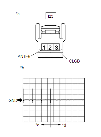
| 13. | CHECK CERTIFICATION ECU (SMART KEY ECU ASSEMBLY) (OUTPUT TO NO. 2 INDOOR ELECTRICAL KEY ANTENNA ASSEMBLY (REAR FLOOR)) |
| (a) Using an oscilloscope, check the waveform. OK:
|
|
| NG | | REPLACE CERTIFICATION ECU (SMART KEY ECU ASSEMBLY) |
|
| 14. | REPLACE NO. 2 INDOOR ELECTRICAL KEY ANTENNA ASSEMBLY (REAR FLOOR) |
(a) Temporarily replace the No. 2 indoor electrical key antenna assembly (rear floor) with a new one.
Click here
|
| 15. | CHECK KEY DIAGNOSTIC MODE |
(a) Check the following antenna in key diagnostic mode.
Body Electrical > Smart Access > Utility| Tester Display |
|---|
| Communication Check(Key Diag Mode) |
(b) Select either channel 1 or channel 2 and inspect the diagnostic mode for each channel.
| (1) Check the No. 2 indoor electrical key antenna assembly (rear floor): When the electrical key transmitter sub-assembly is at either inspection point, check that the wireless buzzer sounds. HINT:
OK: Wireless buzzer sounds. |
|
| OK | | END (NO. 2 INDOOR ELECTRICAL KEY ANTENNA ASSEMBLY (REAR FLOOR) WAS DEFECTIVE) |
| NG | | REPLACE CERTIFICATION ECU (SMART KEY ECU ASSEMBLY) |
| 16. | CHECK HARNESS AND CONNECTOR (CERTIFICATION ECU (SMART KEY ECU ASSEMBLY) - NO. 3 INDOOR ELECTRICAL KEY ANTENNA ASSEMBLY (INSIDE LUGGAGE)) |
(a) Disconnect the I52 certification ECU (smart key ECU assembly) connector.
(b) Disconnect the P15 No. 3 indoor electrical key antenna assembly (inside luggage) connector.
(c) Measure the resistance according to the value(s) in the table below.
Standard Resistance:
| Tester Connection | Condition | Specified Condition |
|---|---|---|
| I52-4 (CLG7) - P15-1 (ANTE7) | Always | Below 1 Ω |
| I52-3 (CG7B) - P15-3 (CLGB) | Always | Below 1 Ω |
| I52-4 (CLG7) or P15-1 (ANTE7) - Body ground | Always | 10 kΩ or higher |
| I52-3 (CG7B) or P15-3 (CLGB) - Body ground | Always | 10 kΩ or higher |
(d) Reconnect the I52 certification ECU (smart key ECU assembly) connector.
| NG | | REPAIR OR REPLACE HARNESS OR CONNECTOR |
|
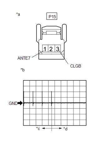
| 17. | CHECK CERTIFICATION ECU (SMART KEY ECU ASSEMBLY) (OUTPUT TO NO. 3 INDOOR ELECTRICAL KEY ANTENNA ASSEMBLY (INSIDE LUGGAGE)) |
| (a) Using an oscilloscope, check the waveform. OK:
|
|
| NG | | REPLACE CERTIFICATION ECU (SMART KEY ECU ASSEMBLY) |
|
| 18. | REPLACE NO. 3 INDOOR ELECTRICAL KEY ANTENNA ASSEMBLY (INSIDE LUGGAGE) |
(a) Replace the No. 3 indoor electrical key antenna assembly (inside luggage).
Click here
|
| 19. | CHECK KEY DIAGNOSTIC MODE |
(a) Check the following antenna in key diagnostic mode.
Body Electrical > Smart Access > Utility| Tester Display |
|---|
| Communication Check(Key Diag Mode) |
(b) Select either channel 1 or channel 2 and inspect the diagnostic mode for each channel.
| (1) Check the No. 3 indoor electrical key antenna assembly (inside luggage): When the electrical key transmitter sub-assembly is at either inspection point, check that the wireless buzzer sounds. HINT:
OK: Wireless buzzer sounds. |
|
| OK | | END (NO. 3 INDOOR ELECTRICAL KEY ANTENNA ASSEMBLY (INSIDE LUGGAGE) WAS DEFECTIVE) |
| NG | | REPLACE CERTIFICATION ECU (SMART KEY ECU ASSEMBLY) |
READ NEXT:
 Entry Interior Alarm does not Sound
DESCRIPTION The smart access system with push-button start (for Entry Function) uses the buzzer in the combination meter assembly (meter ECU) to perform various vehicle interior warnings. When the con
Back Door Entry Unlock Function does not Operate
DESCRIPTION If the entry unlock function does not operate for the back door only, but the entry lock function operates, the request code is being transmitted properly from the back door. In this case,
Back Door Entry Lock and Unlock Functions do not Operate
DESCRIPTION If the entry lock and unlock functions do not operate for the back door only, the request code may not be being transmitted from the back door. If the entry functions for other doors opera
SEE MORE:
Installation
INSTALLATION CAUTION / NOTICE / HINT CAUTION: Wear protective gloves. Sharp areas on the parts may injure your hands. PROCEDURE 1. INSTALL BENCH TYPE REAR SEAT CUSHION COVER (REAR SEAT CUSHION HEATER) HINT:
When installing the seat cover, refer to the precautions in order to prevent wrinkles from
Operation Check
OPERATION CHECK CHECK AIR DUST (a) Check that there are no cracks or damage on the air ducts of the seat climate control blower and seatback climate control blower, and that the air ducts are installed correctly. CHECK CLIMATE CONTROL SEAT SYSTEM (a) Turn the power switch on (IG). (b) Check that the
© 2016-2026 Copyright www.lexunx.com
