Lexus NX: Short Circuit in Power Source Circuit (C13A1)
DESCRIPTION
The following DTCs are stored when a malfunction occurs in the parking brake ECU assembly.
| DTC No. | Detection Item | DTC Detection Condition | Trouble Area | Memory | Note |
|---|---|---|---|---|---|
| C13A1 | Short Circuit in Power Source Circuit | Both of following conditions are met:
|
| Yes | An electric parking brake system malfunction is displayed on the multi-information display. |
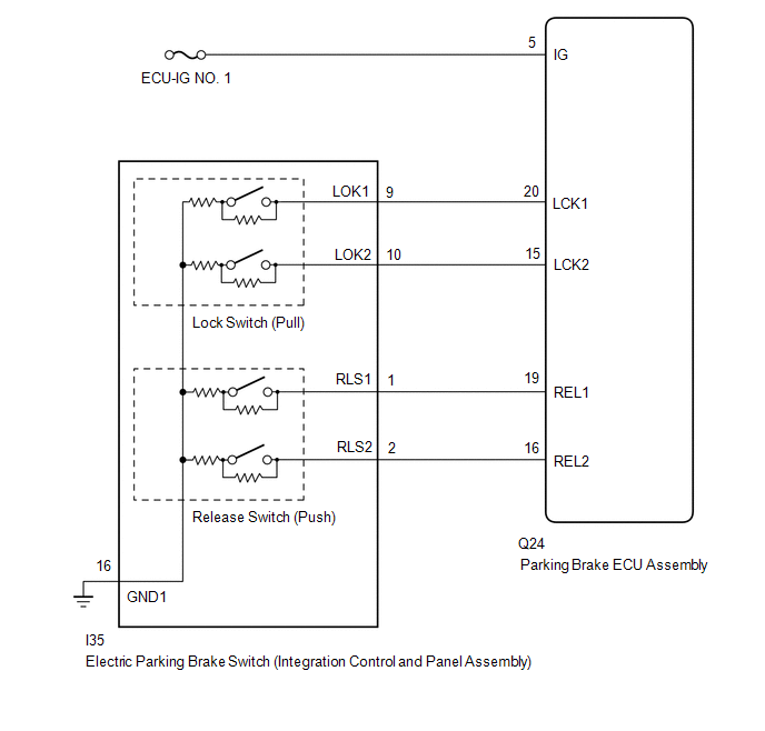
WIRING DIAGRAM
CAUTION / NOTICE / HINT
NOTICE:
- Inspect the fuses for circuits related to this system before performing the following inspection procedure.
- Before disconnecting connectors or fuses, turn the power switch off and wait 20 seconds or more.
- When replacing the parking brake ECU assembly, operate the electric parking brake switch (integration control and panel assembly), as the parking brake indicator light (red) blinks when the power switch is first turned on (IG).
PROCEDURE
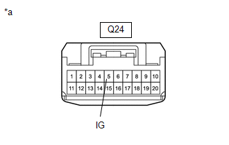
| 1. | CHECK HARNESS AND CONNECTOR (PARKING BRAKE ECU ASSEMBLY - IG POWER SOURCE CIRCUIT) |
| (a) Turn the power switch off. |
|
(b) Disconnect the parking brake ECU assembly connector.
(c) Measure the voltage according to the value(s) in the table below.
Standard Voltage:
| Tester Connection | Switch Condition | Specified Condition |
|---|---|---|
| Q24-5(IG) - Body ground | Power switch off | Below 2.5 V |
| NG | .gif) | REPAIR OR REPLACE HARNESS OR CONNECTOR |
|
.gif)
| 2. | INSPECT ELECTRIC PARKING BRAKE SWITCH (INTEGRATION CONTROL AND PANEL ASSEMBLY) |
(a) Remove the electric parking brake switch (integration control and panel assembly).
Click here .gif)
(b) Inspect the electric parking brake switch (integration control and panel assembly).
Click here
| NG | | REPLACE INTEGRATION CONTROL AND PANEL ASSEMBLY |
|
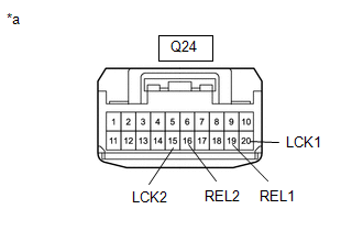
| 3. | CHECK HARNESS AND CONNECTOR (PARKING BRAKE ECU ASSEMBLY - ELECTRIC PARKING BRAKE SWITCH (INTEGRATION CONTROL AND PANEL ASSEMBLY)) |
(a) Disconnect the I35 electric parking brake switch (integration control and panel assembly) connector.
| (b) Disconnect the parking brake ECU assembly connector. |
|
(c) Measure the resistance according to the value(s) in the table below.
Standard Resistance:
| Tester Connection | Condition | Specified Condition |
|---|---|---|
| Q24-20 (LCK1) - Body ground | Always | 10 kΩ or higher |
| Q24-15 (LCK2) - Body ground | Always | 10 kΩ or higher |
| Q24-16 (REL2) - Body ground | Always | 10 kΩ or higher |
| Q24-19 (REL1) - Body ground | Always | 10 kΩ or higher |
| OK | | REPLACE PARKING BRAKE ECU ASSEMBLY |
| NG | | REPAIR OR REPLACE HARNESS OR CONNECTOR |
READ NEXT:
 Engine Switch/Power Switch Malfunction (C13A2)
DESCRIPTION When the power switch is turned on (IG), power is supplied to the parking brake ECU assembly. This DTC is stored if the IG power source is not input to the parking brake ECU assembly when
Open or Short Circuit in Lock Switch Circuit (C13A3,C13AB)
DESCRIPTION When the electric parking brake switch (integration control and panel assembly) is pulled to the lock side, a lock request signal is output to the parking brake ECU assembly. DTC No.
Open or Short Circuit in Release Switch Circuit (C13A4,C13AC)
DESCRIPTION When the electric parking brake switch (integration control and panel assembly) is pushed to the release side, a release request signal is output to the parking brake ECU assembly. DTC
SEE MORE:
Installation
INSTALLATION CAUTION / NOTICE / HINT HINT:
Use the same procedure for the RH and LH sides.
The procedure described below is for the LH side.
PROCEDURE 1. INSTALL SIDE TURN SIGNAL LIGHT ASSEMBLY LH (a) Connect the connector. (b) Align the side turn signal light assembly LH with the alignment
Components
COMPONENTS ILLUSTRATION *1 AIR CONDITIONING CONTROL ASSEMBLY *2 CENTER INSTRUMENT CLUSTER FINISH PANEL ASSEMBLY *3 COWL SIDE TRIM BOARD LH *4 DOOR SCUFF PLATE ASSEMBLY LH *5 INSTRUMENT SIDE PANEL LH *6 INSTRUMENT SIDE PANEL RH *7 LOWER NO. 1 INSTRUMENT PANEL FINIS
