Lexus NX: Shut Down Signal Circuit
DESCRIPTION
The cause of the malfunction may be a shutdown signal.
Check whether there is a shutdown signal +B short circuit.
Related Parts Check| Area | Inspection | Step |
|---|---|---|
| HSDN terminal voltage | Check that the HSDN terminal voltage decreases while READY OFF (IG ON). If the voltage is low, the shutdown signal circuit is normal. | 1 |
| Hybrid vehicle control ECU, inverter | If there is a shutdown signal malfunction, check for whether there is a hybrid vehicle control ECU or inverter malfunction. | 2, 3 |
SYSTEM DESCRIPTION
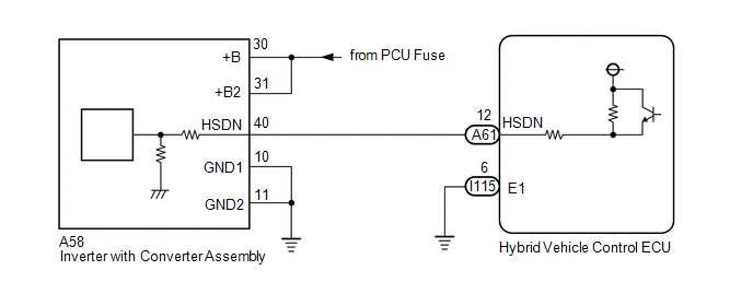
Power supply to the motor is cut off due to a shutdown signal sent from the hybrid vehicle control ECU to the motor generator control ECU (MG ECU).
WIRING DIAGRAM
CAUTION / NOTICE / HINT
This step is referenced from the procedures for each DTC.
If the inspection results below are normal, perform the next procedure for the referenced DTC.
CAUTION:
- Before inspecting the high-voltage system or disconnecting the low voltage connector of the inverter with converter assembly, take safety precautions such as wearing insulated gloves and removing the service plug grip to prevent electrical shocks. After removing the service plug grip, put it in your pocket to prevent other technicians from accidentally reconnecting it while you are working on the high-voltage system.
-
After removing the service plug grip, wait for at least 10 minutes before touching any of the high-voltage connectors or terminals. After waiting for 10 minutes, check the voltage at the terminals in the inspection point in the inverter with converter assembly. The voltage should be 0 V before beginning work.
Click here
.gif)
HINT:
Waiting for at least 10 minutes is required to discharge the high-voltage capacitor inside the inverter with converter assembly.
NOTICE:
After turning the power switch off, waiting time may be required before disconnecting the cable from the negative (-) auxiliary battery terminal. Therefore, make sure to read the disconnecting the cable from the negative (-) auxiliary battery terminal notices before proceeding with work.
Click here
PROCEDURE
| 1. | CHECK HYBRID VEHICLE CONTROL ECU |
(a) Turn the power switch on (IG).
| (b) Measure the voltage according to the value(s) in the table below. Standard Voltage:
|
|
(c) Turn the power switch off.
| OK | .gif) | SHUTDOWN SIGNAL CIRCUIT NORMAL (PERFORM NEXT STEP FOR REFERENCED DTC) |
|
.gif)
| 2. | CHECK HARNESS AND CONNECTOR (HYBRID VEHICLE CONTROL ECU - INVERTER WITH CONVERTER ASSEMBLY) |
CAUTION:
Be sure to wear insulated gloves.
(a) Check that the service plug grip is not installed.
NOTICE:
After removing the service plug grip, do not turn the power switch on (READY), unless instructed by the repair manual because this may cause a malfunction.
(b) Disconnect the A60 and A61 hybrid vehicle control ECU connector.
(c) Disconnect the A58 inverter with converter assembly connector.
Click here
(d) Connect the cable to the negative (-) auxiliary battery terminal.
(e) Turn the power switch on (IG).
(f) Measure the voltage according to the value(s) in the table below.
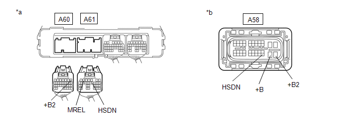
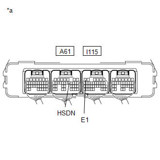
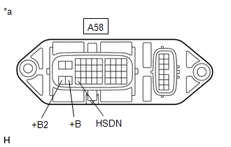
| *a | Rear view of wire harness connector (to Hybrid Vehicle Control ECU) | *b | Front view of wire harness connector (to Inverter with Converter Assembly) |
Standard Voltage:
| Tester Connection | Condition | Specified Condition |
|---|---|---|
| A58-40 (HSDN) or A61-12 (HSDN) - Body ground | Power switch on (IG) | Below 1 V |
NOTICE:
Turning the power switch on (IG) with the hybrid vehicle control ECU and inverter with converter assembly connector disconnected causes other DTCs to be stored. Clear the DTCs after performing this inspection.
(g) Turn the power switch off.
(h) Disconnect the cable from the negative (-) auxiliary battery terminal.
(i) Measure the resistance according to the value(s) in the table below.
Standard Resistance:
| Tester Connection | Condition | Specified Condition |
|---|---|---|
| A58-40 (HSDN) - A58-30 (+B) | Power switch off | 10 kΩ or higher |
| A58-40 (HSDN) - A58-31 (+B2) | Power switch off | 10 kΩ or higher |
| A61-12 (HSDN) - A60-1 (+B2) | Power switch off | 10 kΩ or higher |
| A61-12 (HSDN) - A61-6 (MREL) | Power switch off | 10 kΩ or higher |
(j) Reconnect the A58 inverter with converter assembly connector.
(k) Reconnect the A60 and A61 hybrid vehicle control ECU connector.
| NG | | REPAIR OR REPLACE HARNESS OR CONNECTOR |
|
| 3. | CHECK INVERTER WITH CONVERTER ASSEMBLY |
CAUTION:
Be sure to wear insulated gloves.
(a) Check that the service plug grip is not installed.
NOTICE:
After removing the service plug grip, do not turn the power switch on (READY), unless instructed by the repair manual because this may cause a malfunction.
(b) Disconnect the A58 inverter with converter assembly connector.
| (c) Measure the resistance according to the value(s) in the table below. Standard Resistance:
|
|
(d) Reconnect the A58 inverter with converter assembly connector.
| OK | | REPLACE HYBRID VEHICLE CONTROL ECU |
| NG | | REPLACE INVERTER WITH CONVERTER ASSEMBLY |
READ NEXT:
 Inverter Low-voltage Circuit
DESCRIPTION The cause of the malfunction may be the low-voltage circuit. Check whether there is an open circuit in the inverter +B low-voltage power source system or a problem in the communication bet
HV Battery High-voltage Line Circuit
DESCRIPTION The cause of the malfunction may be the HV battery high-voltage line circuit. Check the continuity in the high-voltage line from the HV battery to the inverter. Check the connection condit
Cooling System
DESCRIPTION The cause of the malfunction may be the cooling system. Check whether the grille is blocked, whether coolant is leaking, the HV radiator fan operating condition and whether coolant has fro
SEE MORE:
Front Airbag Sensor Lost Communication (LH) (B1617,B1618)
DESCRIPTION The front airbag sensor LH circuit consists of the airbag ECU assembly and front airbag sensor LH. The front airbag sensor LH detects impacts to the vehicle and sends signals to the airbag ECU assembly to determine if the airbag should be deployed. DTC B1617 or B1618 is stored when a mal
Washer Nozzle
ComponentsCOMPONENTS ILLUSTRATION *1 HOOD INSULATOR *2 WASHER NOZZLE SUB-ASSEMBLY *3 WASHER HOSE - - ● Non-reusable part - - On-vehicle InspectionON-VEHICLE INSPECTION PROCEDURE 1. INSPECT WASHER NOZZLE SUB-ASSEMBLY (a) With the power switch turned on (IG), check
