Lexus NX: Short in GPS Antenna (B15C0,B15C1)
DESCRIPTION
These DTCs are stored when a malfunction occurs in the navigation antenna assembly.
| DTC No. | Detection Item | DTC Detection Condition | Trouble Area |
|---|---|---|---|
| B15C0 | Short in GPS Antenna | Navigation antenna error |
|
| B15C1 | Open in GPS Antenna | Error of the power source to the navigation antenna |
|
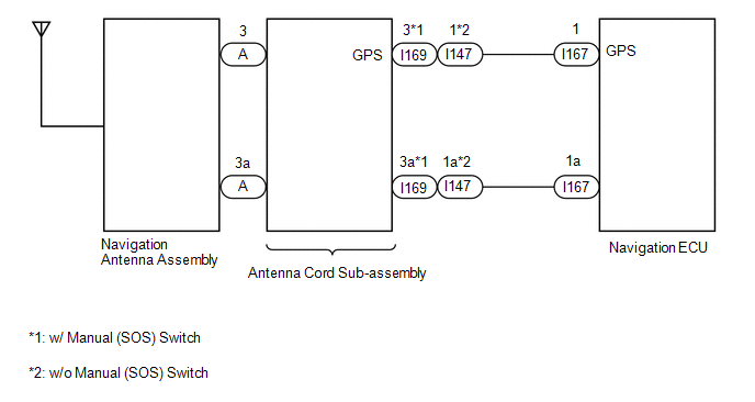
WIRING DIAGRAM
CAUTION / NOTICE / HINT
NOTICE:
When replacing the radio receiver assembly or navigation ECU, always replace it with a new one.
If a radio receiver assembly or navigation ECU which was installed to another vehicle is used, the following may occur:
- A communication malfunction DTC may be stored.
- The radio receiver assembly or navigation ECU may not operate normally.
HINT:
Depending on the parts that are replaced during vehicle inspection or maintenance, performing initialization, registration or calibration may be needed. Refer to Precaution for Navigation System.
Click here .gif)
PROCEDURE
| 1. | CHECK DTC |
(a) Clear the DTCs.
Click here
(b) Recheck for DTCs and check that no DTCs are output.
Click here
OK:
No DTCs are output.
| OK | .gif) | USE SIMULATION METHOD TO CHECK |
|
.gif)
| 2. | INSPECT NAVIGATION ANTENNA ASSEMBLY |
(a) Remove the navigation antenna assembly.
Click here
(b) Inspect the navigation antenna assembly.
Click here
| NG | | REPLACE NAVIGATION ANTENNA ASSEMBLY |
|
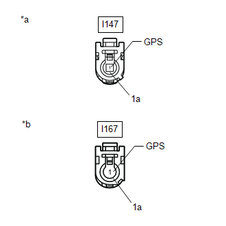
| 3. | CHECK VEHICLE TYPE |
(a) Check the vehicle type.
| Result | Proceed to |
|---|---|
| w/ Manual (SOS) Switch | A |
| w/o Manual (SOS) Switch | B |
| B | | GO TO STEP 8 |
|
| 4. | CHECK ANTENNA CORD SUB-ASSEMBLY |
| (a) Disconnect the antenna connector from the navigation antenna assembly. |
|
(b) Disconnect the antenna connector from the wire harness.
(c) Measure the resistance according to the value(s) in the table below.
Standard Resistance:
| Tester Connection | Condition | Specified Condition |
|---|---|---|
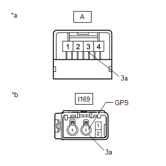
| A-3 - I169-3 (GPS) | Always | Below 1 Ω |
| A-3a - I169-3a | Always | Below 1 Ω |
| A-3 - Body ground | Always | 10 kΩ or higher |
| A-3a - Body ground | Always | 10 kΩ or higher |
| NG | | REPLACE ANTENNA CORD SUB-ASSEMBLY |
|
| 5. | CHECK HARNESS AND CONNECTOR (ANTENNA CORD SUB-ASSEMBLY - NAVIGATION ECU) |
| (a) Disconnect the antenna cord sub-assembly connector. |
|
(b) Disconnect the navigation ECU connector.
(c) Measure the resistance according to the value(s) in the table below.
Standard Resistance:
| Tester Connection | Condition | Specified Condition |
|---|---|---|
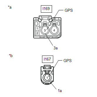
| I169-3 (GPS) - I167-1 (GPS) | Always | Below 1 Ω |
| I169-3a - I167-1a | Always | Below 1 Ω |
| I169-3 (GPS) - Body ground | Always | 10 kΩ or higher |
| I169-3a - Body ground | Always | 10 kΩ or higher |
| NG | | REPAIR OR REPLACE HARNESS OR CONNECTOR |
|
| 6. | REPLACE NAVIGATION ECU |
(a) Replace the navigation ECU with a new one.
Click here
|
| 7. | CHECK DTC |
(a) Clear the DTCs.
Click here
(b) Recheck for DTCs and check that no DTCs are output.
Click here
OK:
No DTCs are output.
| OK | | END (NAVIGATION ECU IS DEFECTIVE) |
| NG | | REPLACE RADIO RECEIVER ASSEMBLY |
| 8. | CHECK ANTENNA CORD SUB-ASSEMBLY |
| (a) Disconnect the antenna connector from the navigation antenna assembly. |
|
(b) Disconnect the antenna connector from the wire harness.
(c) Measure the resistance according to the value(s) in the table below.
Standard Resistance:
| Tester Connection | Condition | Specified Condition |
|---|---|---|
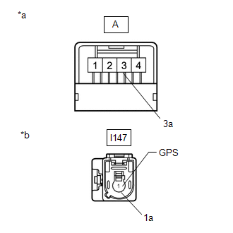
| A-3 - I147-1 (GPS) | Always | Below 1 Ω |
| A-3a - I147-1a | Always | Below 1 Ω |
| A-3 - Body ground | Always | 10 kΩ or higher |
| A-3a - Body ground | Always | 10 kΩ or higher |
| NG | | REPLACE ANTENNA CORD SUB-ASSEMBLY |
|
| 9. | CHECK HARNESS AND CONNECTOR (ANTENNA CORD SUB-ASSEMBLY - NAVIGATION ECU) |
| (a) Disconnect the antenna cord sub-assembly connector. |
|
(b) Disconnect the navigation ECU connector.
(c) Measure the resistance according to the value(s) in the table below.
Standard Resistance:
| Tester Connection | Condition | Specified Condition |
|---|---|---|
| I147-1 (GPS) - I167-1 (GPS) | Always | Below 1 Ω |
| I147-1a - I167-1a | Always | Below 1 Ω |
| I147-1 (GPS) - Body ground | Always | 10 kΩ or higher |
| I147-1a - Body ground | Always | 10 kΩ or higher |
| OK | | GO TO STEP 6 |
| NG | | REPAIR OR REPLACE HARNESS OR CONNECTOR |
READ NEXT:
 Speed Signal Malfunction (B15C2)
DESCRIPTION The navigation ECU receives a vehicle speed signal from the combination meter assembly and information from the navigation antenna, and then adjusts the vehicle position on the map. The na
Speaker Output Short (B15C3)
DESCRIPTION This DTC is stored when a malfunction occurs in the speakers. In addition, the radio receiver assembly detects a malfunction via the stereo component amplifier assembly. DTC No. Detec
MOST Communication Malfunction (B15D0)
DESCRIPTION Navigation system components communicate with each other via MOST communication. If a line short or short to ground occurs in a MOST communication line, communication will not be possible
SEE MORE:
Removal
REMOVAL PROCEDURE 1. REMOVE REAR SEAT ASSEMBLY (a) for Manual Seat: Click here (b) for Power Seat: Click here 2. REMOVE REAR FLOOR FINISH PLATE Click here 3. DISCONNECT REAR DOOR OPENING TRIM WEATHERSTRIP RH Click here 4. REMOVE UPPER DECK TRIM SIDE BOARD RH Click here 5. REMOVE ROPE HO
System Description
SYSTEM DESCRIPTION ILLUMINATION CONTROL SYSTEM (Illuminated Entry System) HINT: When inspecting the following functions, make sure that the map light switch and spot light switch are in the DOOR position. (a) The illuminated entry system has the following control functions: Control Outline Li
