Lexus NX: Terminals Of Ecu
TERMINALS OF ECU
CHECK INSTRUMENT PANEL JUNCTION BLOCK ASSEMBLY, MAIN BODY ECU (MULTIPLEX NETWORK BODY ECU)
(a) Remove the main body ECU (multiplex network body ECU) from the instrument panel junction block assembly.
Click here .gif)
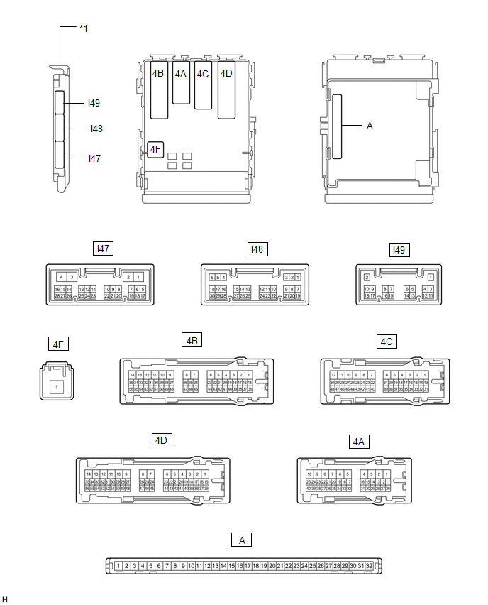
| *1 | Main Body ECU (Multiplex Network Body ECU) | - | - |
(b) Connect the instrument panel junction block assembly connectors.
(c) Measure the voltage and resistance according to the value(s) in the table below.
| Terminal No. (Symbol) | Wiring Color | Terminal Description | Condition | Specified Condition |
|---|---|---|---|---|
| A-32 (IG) - Body ground | - | Ignition power supply | Power switch off | Below 1 V |
| Power switch on (IG) | 11 to 14 V | |||
| A-31 (BECU) - Body ground | - | Battery power supply | Power switch off | 11 to 14 V |
| A-30 (ACC) - Body ground | - | ACC power supply | Power switch off | Below 1 V |
| Power switch on (ACC) | 11 to 14 V | |||
| A-11 (GND1) - Body ground | - | Ground | Always | Below 1 Ω |
If the result is not as specified, there may be a malfunction in the wire harness or instrument panel junction block assembly.
(d) Install the main body ECU (multiplex network body ECU).
Click here
(e) Measure the voltage and pulse according to the value(s) in the table below.
| Terminal No. (Symbol) | Wiring Color | Terminal Description | Condition | Specified Condition |
|---|---|---|---|---|
| I48-1 (DIM) - Body ground | L - Body ground | H-LP RH relay drive output | Power switch off | 11 to 14 V |
| Power switch on (IG) | Below 1 V | |||
| I48-8 (A) - Body ground | G - Body ground | Headlight dimmer switch AUTO signal input | Headlight dimmer switch not in AUTO position | 11 to 14 V |
| Headlight dimmer switch in AUTO position | Below 1 V | |||
| I48-3 (RLEW) - Body ground | P - Body ground | LED headlight signal input | Headlight dimmer switch in AUTO position and automatic light control sensor covered with a hand (Turn off the headlights) | Below 1 V |
| Headlight dimmer switch in head position | Pulse generation | |||
| I48-10 (HF) - Body ground | R - Body ground | Headlight dimmer switch high flash signal input | Headlight dimmer switch not in high flash position | 11 to 14 V |
| Headlight dimmer switch in high flash position | Below 1 V | |||
| I48-12 (HEAD) - Body ground | LG - Body ground | Headlight dimmer switch head signal input | Headlight dimmer switch not in head position | 11 to 14 V |
| Headlight dimmer switch in head position | Below 1 V | |||
| I48-16 (LLEW) - Body ground | G - Body ground | LED headlight signal input | Headlight dimmer switch in AUTO position and automatic light control sensor covered with a hand (Turn off the headlights) | Below 1 V |
| Headlight dimmer switch in head position | Pulse generation | |||
| I48-19 (CLTB) - I48-21 (CLTE) | W - V | Automatic light control sensor power supply output | Power switch on (IG) | 11 to 14 V |
| I48-22 (TAIL) - Body ground | P - Body ground | Headlight dimmer switch tail signal input | Headlight dimmer switch in neither tail nor head position | 11 to 14 V |
| Headlight dimmer switch in tail or head position | Below 1 V | |||
| I48-24 (HU) - Body ground | Y - Body ground | Headlight dimmer switch high signal input | Headlight dimmer switch in low position | 11 to 14 V |
| Headlight dimmer switch in high position | Below 1 V | |||
| I48-26 (FFOG) - Body ground | GR - Body ground | Front fog light switch input | Front fog light switch off | 11 to 14 V |
| Front fog light switch on | Below 1 V | |||
| 4B-53 (HRLY) - Body ground | L - Body ground | H-LP LH DIMMER (HI) relay drive output | Power switch off | 11 to 14 V |
| Power switch on (IG) | Below 1 V | |||
| 4B-56 (FFGO) - Body ground | W - Body ground | Front fog light signal output | Headlight dimmer switch in tail or head position and front fog light switch off | 11 to 14 V |
| Headlight dimmer switch in tail or head position and front fog light switch on | Below 1 V | |||
| 4F-1 (TRLY) - Body ground | W - Body ground | TAIL relay drive signal | Headlight dimmer switch not in tail position | 11 to 14 V |
| Headlight dimmer switch in tail position | Below 1 V | |||
| I48-20 (CLTS) - Body ground | P - Body ground | Automatic light control sensor signal input | Power switch on (IG), headlight dimmer switch in AUTO position and automatic light control sensor covered with a hand → Automatic light control sensor exposed to ambient light | Pulse generation (waveform varies depending on light volume) |
| I48-6 (FLCY) - Body ground | G - Body ground | Front door courtesy light switch LH signal | Front door LH open | Below 1 V |
| Front door LH closed | Pulse generation |
CHECK COMBINATION METER ASSEMBLY
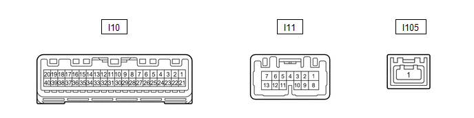
(a) Disconnect the I10 and I11 combination meter connectors.
(b) Measure the resistance and voltage according to the value(s) in the table below.
| Terminal No. (Symbol) | Wiring Color | Terminal Description | Condition | Specified Condition |
|---|---|---|---|---|
| I10-22 (B) - Body ground | Y - Body ground | Battery power supply | Power switch off | 11 to 14 V |
| I10-21 (IG+) - Body ground | B - Body ground | Ignition power supply | Power switch off | Below 1 V |
| Power switch on (IG) | 9.5 to 14 V | |||
| I11-1 (B) - Body ground | L - Body ground | Battery power supply | Power switch off | 11 to 14 V |
| I11-2 (HZSW) - Body ground | B - Body ground | Hazard warning signal switch signal input | Hazard warning signal switch off | 11 to 14 V |
| Hazard warning signal switch on | Below 1 V | |||
| I11-12 (HAZM) - Body ground | R - Body ground | Hazard warning signal switch signal input | Hazard warning signal switch off | Below 1 V → 11 to 14 V |
| Hazard warning signal switch on | Below 1 V | |||
| I10-40 (EP) - Body ground | W-B - Body ground | Ground | Always | Below 1 Ω |
(c) Reconnect the I10 and I11 combination meter connectors.
(d) Measure the voltage according to the value(s) in the table below.
| Terminal No. (Symbol) | Wiring Color | Terminal Description | Condition | Specified Condition |
|---|---|---|---|---|
| I11-3 (ER) - Body ground | L - Body ground | Turn signal switch (right turn position) signal input | Power switch on (IG) Turn signal switch off | 11 to 14 V |
| Power switch on (IG) Turn signal switch in right turn position | Below 1 V | |||
| I11-4 (EL) - Body ground | R - Body ground | Turn signal switch (left turn position) signal input | Power switch on (IG) Turn signal switch off | 11 to 14 V |
| Power switch on (IG) Turn signal switch in left turn position | Below 1 V | |||
| I11-8 (SW) - Body ground | B - Body ground | Turn signal switch (full turn position) signal input | Power switch on (IG) Turn signal switch off | 11 to 14 V |
| Power switch on (IG) Turn signal switch in full turn position | Below 1 V | |||
| I11-7 (LR) - Body ground | L - Body ground | RH turn signal light signal output | Power switch on (IG) RH turn signal light off | Below 1 V |
| Power switch on (IG) RH turn signal light blinking | Below 1 V ←→ 11 to 14 V | |||
| I11-13 (LL) - Body ground | Y - Body ground | LH turn signal light signal output | Power switch on (IG) LH turn signal light off | Below 1 V |
| Power switch on (IG) RH turn signal light blinking | Below 1 V ←→ 11 to 14 V | |||
| I11-5 (TRNR) - Body ground | SB - Body ground | RH turn signal light signal output | Power switch on (IG) RH turn signal light off | Below 1 V |
| Power switch on (IG) RH turn signal light blinking | Below 1 V ←→ 11 to 14 V | |||
| I11-11 (TRNL) - Body ground | Y - Body ground | LH turn signal light signal output | Power switch on (IG) LH turn signal light off | Below 1 V |
| Power switch on (IG) RH turn signal light blinking | Below 1 V ←→ 11 to 14 V |
READ NEXT:
 Dtc Check / Clear
DTC CHECK / CLEAR CHECK FOR DTC (a) Connect the Techstream to the DLC3. (b) Turn the power switch on (IG). (c) Turn the Techstream on. (d) Enter the following menus: Body Electrical / Main body / Trou
Freeze Frame Data
FREEZE FRAME DATA FREEZE FRAME DATA (a) Whenever a lighting system DTC is stored, the forward recognition camera stores the current vehicle state as freeze frame data. CHECK FREEZE FRAME DATA (a) Conn
Fail-safe Chart
FAIL-SAFE CHART LED HEADLIGHT SYSTEM The headlight assembly (light control LED ECU) operates in fail-safe mode if any of the following abnormalities are detected. Item Abnormality Detection Condi
SEE MORE:
Inspection
INSPECTION PROCEDURE 1. INSPECT BACK DOOR OPENER SWITCH ASSEMBLY (a) Check the operation of the opener switch. (1) Measure the resistance according to the value(s) in the table below. Standard Resistance: Tester Connection Switch Condition Specified Condition 1 (UL) - 2 (E) Back doo
Disassembly
DISASSEMBLY CAUTION / NOTICE / HINT HINT:
Use the same procedure for the RH and LH side.
The procedure listed below is for the LH side.
PROCEDURE 1. PRECAUTION NOTICE: After turning the power switch off, waiting time may be required before disconnecting the cable from the auxiliary battery n
