Lexus NX: Speaker Output Short (B15C3)
DESCRIPTION
This DTC is stored when a malfunction occurs in the speakers.
In addition, the radio receiver assembly detects a malfunction via the stereo component amplifier assembly.
| DTC No. | Detection Item | DTC Detection Condition | Trouble Area |
|---|---|---|---|
| B15C3 | Speaker Output Short | A short is detected in the speaker output circuit |
|
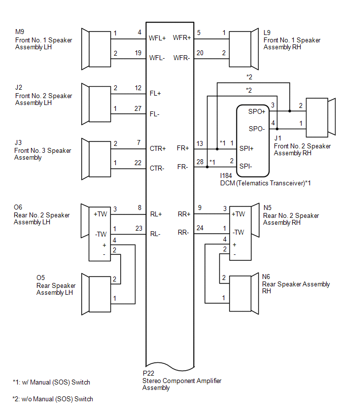
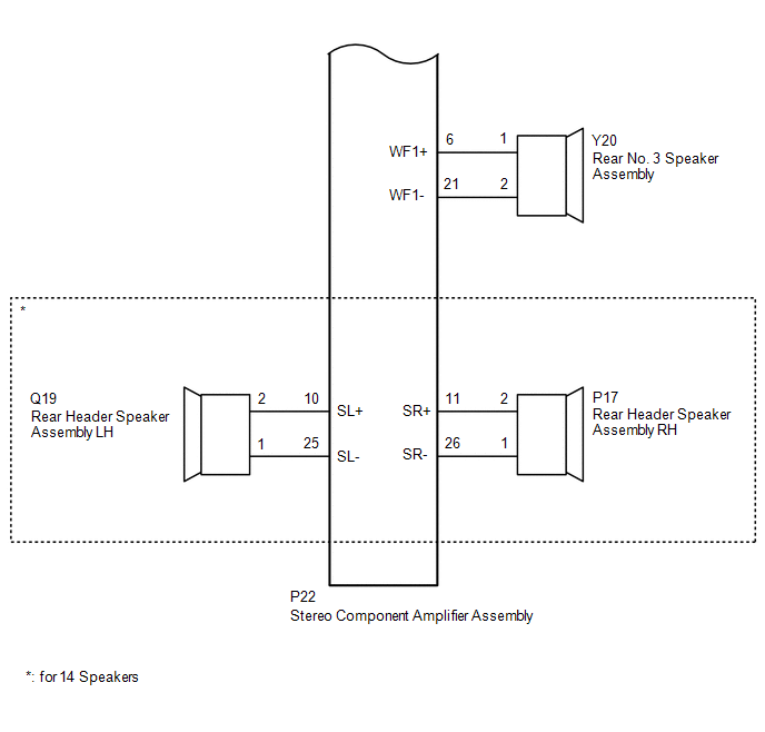
WIRING DIAGRAM
CAUTION / NOTICE / HINT
NOTICE:
When replacing the DCM (telematics transceiver), make sure to replace it with a new one (w/ Manual [SOS] Switch).
HINT:
Depending on the parts that are replaced during vehicle inspection or maintenance, performing initialization, registration or calibration may be needed. Refer to Precaution for Navigation System.
Click here .gif)
PROCEDURE
| 1. | CHECK DTC |
(a) Clear the DTCs.
Click here
(b) Recheck for DTCs and check that no DTCs are output.
Click here
OK:
No DTCs are output.
| OK | .gif) | USE SIMULATION METHOD TO CHECK |
|
.gif)
| 2. | CHECK HARNESS AND CONNECTOR (SPEAKER CIRCUIT) |
-
*1: for LH Side
*2: for RH Side
*3: for 14 Speakers
*4: w/ Manual (SOS) Switch
(a) Disconnect the P22 stereo component amplifier assembly connector.
(b) Disconnect the M9*1 and/or L9*2 front No. 1 speaker assembly connector.
(c) Disconnect the J2*1 and/or J1*2 front No. 2 speaker assembly connector.
(d) Disconnect the J3 front No. 3 speaker assembly connector.
(e) Disconnect the O6*1 and/or N5*2 rear No. 2 speaker assembly connector.
(f) Disconnect the O5*1 and/or N6*2 rear speaker assembly connector.
(g) Disconnect the Y20 rear No. 3 speaker assembly connector.
(h) Disconnect the Q19*1 and/or P17*2 rear header speaker assembly connector.*3
(i) Disconnect the I184 DCM (telematics transceiver) connector.*4
(j) Measure the resistance according to the value(s) in the table below.
Standard Resistance:
for LH Side| Tester Connection | Condition | Specified Condition |
|---|---|---|
| P22-4 (WFL+) - M9-1 | Always | Below 1 Ω |
| P22-19 (WFL-) - M9-2 | Always | Below 1 Ω |
| P22-12 (FL+) - J2-2 | Always | Below 1 Ω |
| P22-27 (FL-) - J2-1 | Always | Below 1 Ω |
| P22-8 (RL+) - O6-3 (+TW) | Always | Below 1 Ω |
| P22-23 (RL-) - O6-1 (-TW) | Always | Below 1 Ω |
| O6-4 (+) - O5-1 | Always | Below 1 Ω |
| O6-2 (-) - O5-2 | Always | Below 1 Ω |
| P22-10 (SL+) - Q19-2*3 | Always | Below 1 Ω |
| P22-25 (SL-) - Q19-1*3 | Always | Below 1 Ω |
| P22-4 (WFL+) - Body ground | Always | 10 kΩ or higher |
| P22-19 (WFL-) - Body ground | Always | 10 kΩ or higher |
| P22-12 (FL+) - Body ground | Always | 10 kΩ or higher |
| P22-27 (FL-) - Body ground | Always | 10 kΩ or higher |
| P22-8 (RL+) - Body ground | Always | 10 kΩ or higher |
| P22-23 (RL-) - Body ground | Always | 10 kΩ or higher |
| O6-4 (+) - Body ground | Always | 10 kΩ or higher |
| O6-2 (-) - Body ground | Always | 10 kΩ or higher |
| P22-10 (SL+) - Body ground*3 | Always | 10 kΩ or higher |
| P22-25 (SL-) - Body ground*3 | Always | 10 kΩ or higher |
| Tester Connection | Condition | Specified Condition |
|---|---|---|
| P22-5 (WFR+) - L9-1 | Always | Below 1 Ω |
| P22-20 (WFR-) - L9-2 | Always | Below 1 Ω |
| P22-13 (FR+) - I184-1 (SPI+) | Always | Below 1 Ω |
| P22-28 (FR-) - I184-2 (SPI-) | Always | Below 1 Ω |
| I184-3 (SPO+) - J1-2 | Always | Below 1 Ω |
| I184-4 (SPO-) - J1-1 | Always | Below 1 Ω |
| P22-9 (RR+) - N5-3 (+TW) | Always | Below 1 Ω |
| P22-24 (RR-) - N5-1 (-TW) | Always | Below 1 Ω |
| N5-4 (+) - N6-1 | Always | Below 1 Ω |
| N5-2 (-) - N6-2 | Always | Below 1 Ω |
| P22-11 (SR+) - P17-2*3 | Always | Below 1 Ω |
| P22-26 (SR-) - P17-1*3 | Always | Below 1 Ω |
| P22-5 (WFR+) - Body ground | Always | 10 kΩ or higher |
| P22-20 (WFR-) - Body ground | Always | 10 kΩ or higher |
| P22-13 (FR+) - Body ground | Always | 10 kΩ or higher |
| P22-28 (FR-) - Body ground | Always | 10 kΩ or higher |
| I184-3 (SPO+) - Body ground | Always | 10 kΩ or higher |
| I184-4 (SPO-) - Body ground | Always | 10 kΩ or higher |
| P22-9 (RR+) - Body ground | Always | 10 kΩ or higher |
| P22-24 (RR-) - Body ground | Always | 10 kΩ or higher |
| N5-4 (+) - Body ground | Always | 10 kΩ or higher |
| N5-2 (-) - Body ground | Always | 10 kΩ or higher |
| P22-11 (SR+) - Body ground*3 | Always | 10 kΩ or higher |
| P22-26 (SR-) - Body ground*3 | Always | 10 kΩ or higher |
| Tester Connection | Condition | Specified Condition |
|---|---|---|
| P22-5 (WFR+) - L9-1 | Always | Below 1 Ω |
| P22-20 (WFR-) - L9-2 | Always | Below 1 Ω |
| P22-13 (FR+) - J1-2 | Always | Below 1 Ω |
| P22-28 (FR-) - J1-1 | Always | Below 1 Ω |
| P22-9 (RR+) - N5-3 (+TW) | Always | Below 1 Ω |
| P22-24 (RR-) - N5-1 (-TW) | Always | Below 1 Ω |
| N5-4 (+) - N6-1 | Always | Below 1 Ω |
| N5-2 (-) - N6-2 | Always | Below 1 Ω |
| P22-11 (SR+) - P17-2*3 | Always | Below 1 Ω |
| P22-26 (SR-) - P17-1*3 | Always | Below 1 Ω |
| P22-5 (WFR+) - Body ground | Always | 10 kΩ or higher |
| P22-20 (WFR-) - Body ground | Always | 10 kΩ or higher |
| P22-13 (FR+) - Body ground | Always | 10 kΩ or higher |
| P22-28 (FR-) - Body ground | Always | 10 kΩ or higher |
| P22-9 (RR+) - Body ground | Always | 10 kΩ or higher |
| P22-24 (RR-) - Body ground | Always | 10 kΩ or higher |
| N5-4 (+) - Body ground | Always | 10 kΩ or higher |
| N5-2 (-) - Body ground | Always | 10 kΩ or higher |
| P22-11 (SR+) - Body ground*3 | Always | 10 kΩ or higher |
| P22-26 (SR-) - Body ground*3 | Always | 10 kΩ or higher |
| Tester Connection | Condition | Specified Condition |
|---|---|---|
| P22-7 (CTR+) - J3-2 | Always | Below 1 Ω |
| P22-22 (CTR-) - J3-1 | Always | Below 1 Ω |
| P22-6 (WF1+) - Y20-1 | Always | Below 1 Ω |
| P22-21 (WF1-) - Y20-2 | Always | Below 1 Ω |
| P22-7 (CTR+) - Body ground | Always | 10 kΩ or higher |
| P22-22 (CTR-) - Body ground | Always | 10 kΩ or higher |
| P22-6 (WF1+) - Body ground | Always | 10 kΩ or higher |
| P22-21 (WF1-) - Body ground | Always | 10 kΩ or higher |
| NG | | REPAIR OR REPLACE HARNESS OR CONNECTOR |
|
| 3. | INSPECT FRONT NO. 1 SPEAKER ASSEMBLY |
(a) Remove the front No. 1 speaker assembly.
Click here
(b) Inspect the front No. 1 speaker assembly.
Click here
| NG | | REPLACE FRONT NO. 1 SPEAKER ASSEMBLY |
|
| 4. | INSPECT FRONT NO. 2 SPEAKER ASSEMBLY |
(a) Remove the front No. 2 speaker assembly.
Click here
(b) Inspect the front No. 2 speaker assembly.
Click here
| NG | | REPLACE FRONT NO. 2 SPEAKER ASSEMBLY |
|
| 5. | INSPECT FRONT NO. 3 SPEAKER ASSEMBLY |
(a) Remove the front No. 3 speaker assembly.
Click here
(b) Inspect the front No. 3 speaker assembly.
Click here
| NG | | REPLACE FRONT NO. 3 SPEAKER ASSEMBLY |
|
| 6. | INSPECT REAR SPEAKER ASSEMBLY |
(a) Remove the rear speaker assembly.
Click here
(b) Inspect the rear speaker assembly.
Click here
| NG | | REPLACE REAR SPEAKER ASSEMBLY |
|
| 7. | INSPECT REAR NO. 3 SPEAKER ASSEMBLY |
(a) Remove the rear No. 3 speaker assembly.
Click here
(b) Inspect the rear No. 3 speaker assembly.
Click here
| NG | | REPLACE REAR NO. 3 SPEAKER ASSEMBLY |
|
| 8. | CHECK VEHICLE TYPE |
(a) Check the vehicle type.
| Result | Proceed to |
|---|---|
| for 14 Speakers | A |
| for 10 Speakers | B |
| B | | GO TO STEP 10 |
|
| 9. | INSPECT REAR HEADER SPEAKER ASSEMBLY |
(a) Remove the rear header speaker assembly.
Click here
(b) Inspect the rear header speaker assembly.
Click here
| NG | | REPLACE REAR HEADER SPEAKER ASSEMBLY |
|
| 10. | CHECK VEHICLE TYPE |
(a) Check the vehicle type.
| Result | Proceed to |
|---|---|
| w/ Manual (SOS) Switch | A |
| w/o Manual (SOS) Switch | B |
| B | | GO TO STEP 12 |
|
| 11. | INSPECT DCM (TELEMATICS TRANSCEIVER) (SPO+, SPO-, SPI+, SPI-) |
| (a) Remove the DCM (telematics transceiver). Click here |
|
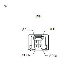
(b) Measure the resistance according to the value(s) in the table below.
Standard Resistance:
| Tester Connection | Condition | Specified Condition |
|---|---|---|
| I184-1 (SPI+) - I184-3 (SPO+) | Always | Below 1 Ω |
| I184-2 (SPI-) - I184-4 (SPO-) | Always | Below 1 Ω |
| I184-1 (SPI+) - I184-2 (SPI-) | Always | 10 kΩ or higher |
| I184-3 (SPO+) - I184-4 (SPO-) | Always | 10 kΩ or higher |
| NG | | REPLACE DCM (TELEMATICS TRANSCEIVER) |
|
| 12. | CHECK REAR NO. 2 SPEAKER ASSEMBLY |
(a) Replace the rear No. 2 speaker assembly with a new or known good one.
Click here
(b) Clear the DTCs.
Click here
(c) Recheck for DTCs and check that no DTCs are output.
Click here
OK:
No DTCs are output.
| OK | | END (REAR NO. 2 SPEAKER ASSEMBLY IS DEFECTIVE) |
| NG | | REPLACE STEREO COMPONENT AMPLIFIER ASSEMBLY |
READ NEXT:
 MOST Communication Malfunction (B15D0)
DESCRIPTION Navigation system components communicate with each other via MOST communication. If a line short or short to ground occurs in a MOST communication line, communication will not be possible
Stereo Component Amplifier Disconnected (B15D3)
DESCRIPTION The radio receiver assembly and stereo component amplifier assembly are connected by the MOST communication line. This DTC is stored when a MOST communication error occurs between the radi
Display Disconnected (B15D6)
DESCRIPTION The multi-display assembly and radio receiver assembly are connected by the AVC-LAN communication line. This DTC is stored when an AVC-LAN communication error occurs between the multi-disp
SEE MORE:
Vehicles Speed Malfunction (B2624)
DESCRIPTION The multiplex tilt and telescopic ECU forms a network with the ECUs of other systems via CAN communication. Each ECU informs the other ECUs that it is connected to the network by sending a specified signal (periodic signal) onto the communication bus on a regular basis. The multiplex til
Diagnostic Trouble Code Chart
DIAGNOSTIC TROUBLE CODE CHART Power Window Control System DTC No. Detection Item Link B2311 Power Window Motor Malfunction B2311 Power Window Motor Malfunction B2311 Power Window Motor Malfunction B2311 Power Window Motor Malfunction B2312 Pow
