Lexus NX: Sound Signal Circuit between Radio Receiver and Stereo Jack Adapter
DESCRIPTION
The No. 1 stereo jack adapter assembly sends the sound signal from an external device to the radio receiver assembly via this circuit.
The sound signal that has been sent is amplified by the stereo component amplifier assembly and then is sent to the speakers.
If there is an open or short in the circuit, sound cannot be heard from the speakers even if there is no malfunction in the stereo component amplifier assembly, radio receiver assembly or speakers.
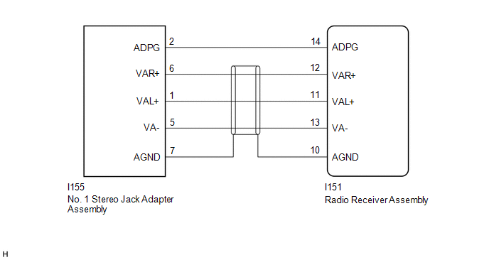
WIRING DIAGRAM
PROCEDURE
| 1. | CHECK HARNESS AND CONNECTOR (RADIO RECEIVER ASSEMBLY - NO. 1 STEREO JACK ADAPTER ASSEMBLY) |
(a) Disconnect the I151 radio receiver assembly connector.
(b) Disconnect the I155 No. 1 stereo jack adapter assembly connector.
(c) Measure the resistance according to the value(s) in the table below.
Standard Resistance:
| Tester Connection | Condition | Specified Condition |
|---|---|---|
| I151-14 (ADPG) - I155-2 (ADPG) | Always | Below 1 Ω |
| I151-10 (AGND) - I155-7 (AGND) | Always | Below 1 Ω |
| I151-11 (VAL+) - I155-1 (VAL+) | Always | Below 1 Ω |
| I151-12 (VAR+) - I155-6 (VAR+) | Always | Below 1 Ω |
| I151-13 (VA-) - I155-5 (VA-) | Always | Below 1 Ω |
| I151-14 (ADPG) or I155-2 (ADPG) - Body ground | Always | 10 kΩ or higher |
| I151-10 (AGND) or I155-7 (AGND) - Body ground | Always | 10 kΩ or higher |
| I151-11 (VAL+) or I155-1 (VAL+) - Body ground | Always | 10 kΩ or higher |
| I151-12 (VAR+) or I155-6 (VAR+) - Body ground | Always | 10 kΩ or higher |
| I151-13 (VA-) or I155-5 (VA-) - Body ground | Always | 10 kΩ or higher |
| OK | .gif) | PROCEED TO NEXT SUSPECTED AREA SHOWN IN PROBLEM SYMPTOMS TABLE |
.gif)
| NG | | REPAIR OR REPLACE HARNESS OR CONNECTOR |
READ NEXT:
 Data Signal Circuit between Radio Receiver and Stereo Jack Adapter
DESCRIPTION The No. 1 stereo jack adapter assembly sends the sound data signal or image data signal from a USB device to the radio receiver assembly via this circuit. WIRING DIAGRAM PROCEDURE 1.
Mute Signal Circuit between Radio Receiver and Stereo Component Amplifier
DESCRIPTION This circuit sends a signal to the stereo component amplifier assembly to mute noise. Because of that, the noise produced by changing the sound source ceases. If there is an open in the ci
Mute Signal Circuit between Stereo Component Amplifier and Telematics Transceiver
DESCRIPTION This DCM (telematics transceiver) sends a mute signal to the stereo component amplifier assembly. The stereo component amplifier assembly controls the volume according to the mute signal f
SEE MORE:
Lost Communication with Gateway Module (Main Body ECU) (U1002)
DESCRIPTION
The main body ECU (multiplex network body ECU) will store this DTC when no signals can be received from the ECUs that have been memorized as those that are connected to sub bus 1.
When the main body ECU (multiplex network body ECU) receives a response signal from the ECUs connected
Removal
REMOVAL CAUTION / NOTICE / HINT HINT:
Use the same procedure for the RH and LH sides.
The procedure described below is for the LH side.
PROCEDURE 1. REMOVE OUTER MIRROR LH Click here 2. REMOVE OUTER MIRROR COVER LH (a) Detach the 6 claws and 2 guides and remove the outer mirror cover L
