Lexus NX: Removal
REMOVAL
CAUTION / NOTICE / HINT
HINT:
- Use the same procedure for the RH and LH sides.
- The procedure described below is for the LH side.
PROCEDURE
1. REMOVE OUTER MIRROR LH
Click here .gif)
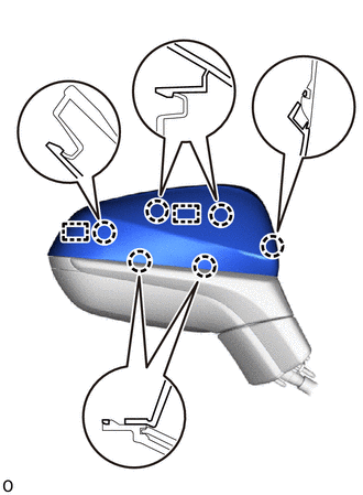
2. REMOVE OUTER MIRROR COVER LH
| (a) Detach the 6 claws and 2 guides and remove the outer mirror cover LH. |
|
3. REMOVE OUTER MIRROR BEZEL LH
| (a) Remove the screw. |
|
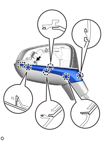
(b) Detach the 5 claws and guide and outer mirror bezel LH.
4. REMOVE LOWER OUTER MIRROR COVER LH
| (a) w/ Panoramic View Monitor System: Disconnect the connector and detach the wire harness clamp. |
|
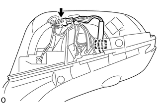
| (b) Remove the screw. |
|
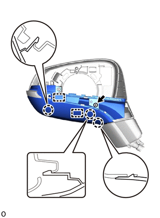
(c) Detach the claw and 2 guides and lower outer mirror cover LH.
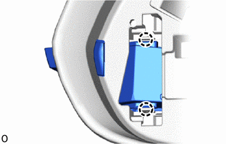
5. REMOVE SIDE TURN SIGNAL LIGHT ASSEMBLY LH
| (a) Detach the 2 claws and remove the side turn signal light assembly LH. |
|
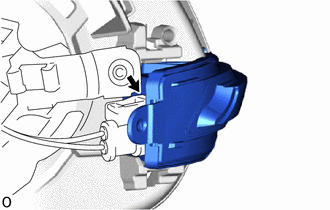
| (b) Disconnect the connector. |
|
READ NEXT:
 Inspection
INSPECTION PROCEDURE 1. INSPECT SIDE TURN SIGNAL LIGHT ASSEMBLY LH (a) Apply auxiliary battery voltage to the connector and check the light illumination condition. OK: Condition Specified Con
Installation
INSTALLATION CAUTION / NOTICE / HINT HINT:
Use the same procedure for the RH and LH sides.
The procedure described below is for the LH side.
PROCEDURE 1. INSTALL SIDE TURN SIGNAL LIGHT ASSEMBL
SEE MORE:
Removal
REMOVAL CAUTION / NOTICE / HINT NOTICE:
When the brake pedal is first depressed after replacing the brake pads or pushing back the disc brake piston, DTC C1214 may be output. As there is no malfunction, clear the DTC.
While the auxiliary battery is connected, even if the power switch is off, th
Disassembly
DISASSEMBLY PROCEDURE 1. PRECAUTION NOTICE:
Be sure to read Precaution thoroughly before servicing.
Click here
Do not reuse parts which have reduced fastening ability due to thread damage.
When installing components, make sure that the wire harness is not pinched or pulled.
Do not use sol
© 2016-2026 Copyright www.lexunx.com
