Lexus NX: Status Signal Circuit
DESCRIPTION
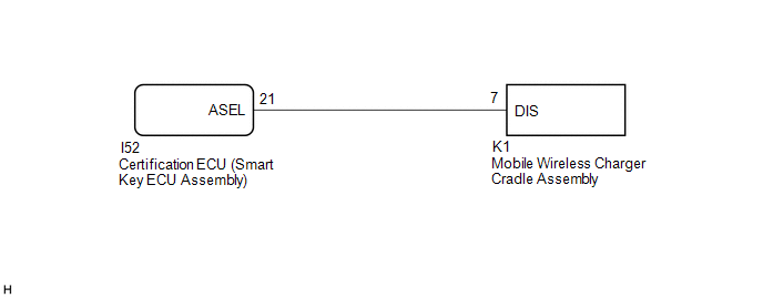
This circuit sends a charging stop signal from the certification ECU (smart key ECU assembly) to the mobile wireless charger cradle assembly. Based on this signal, the wireless charging system stops the charging operation.
HINT:
The charging frequency of the wireless charging system overlaps with the electrical wave frequency band that is used when the entry and start system detects the position of the electrical key transmitter sub-assembly. Therefore, when the electrical key transmitter sub-assembly position is being detected, the charging stop signal from the certification ECU (smart key ECU assembly) makes the wireless charging system stop charging.
WIRING DIAGRAM
PROCEDURE
| 1. | CHECK MOBILE WIRELESS CHARGER CRADLE ASSEMBLY |
| (a) Measure the voltage according to the value(s) in the table below. Standard Voltage:
HINT: Check with the certification ECU (smart key ECU assembly) connector connected. |
| |||||||||||||||||
.gif) .
.
| OK | .gif) | PROCEED TO NEXT SUSPECTED AREA SHOWN IN PROBLEM SYMPTOMS TABLE |
|
.gif)
| 2. | CHECK HARNESS AND CONNECTOR (MOBILE WIRELESS CHARGER CRADLE ASSEMBLY - CERTIFICATION ECU [SMART KEY ECU ASSEMBLY]) |
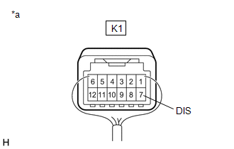
(a) Disconnect the K1 mobile wireless charger cradle assembly connector.
(b) Disconnect the I52 certification ECU (smart key ECU assembly) connector.
(c) Measure the resistance according to the value(s) in the table below.
Standard Resistance:
| Tester Connection | Condition | Specified Condition |
|---|---|---|
| K1-7 (DIS) - I52-21 (ASEL) | Always | Below 1 Ω |
| K1-7 (DIS) or I52-21 (ASEL) - Body ground | Always | 10 kΩ or higher |
| OK | | REPLACE CERTIFICATION ECU (SMART KEY ECU ASSEMBLY) |
| NG | | REPAIR OR REPLACE HARNESS OR CONNECTOR |
READ NEXT:
 Precaution
PRECAUTION PRECAUTION FOR DISCONNECTING CABLE FROM NEGATIVE AUXILIARY BATTERY TERMINAL NOTICE:
When disconnecting the cable from the negative (-) auxiliary battery terminal, initialize the some sys
SEE MORE:
Data List / Active Test
DATA LIST / ACTIVE TEST DATA LIST NOTICE: In the table below, the values listed under "Normal Condition" are reference values. Do not depend solely on these reference values when deciding whether a part is faulty or not. HINT: Using the Techstream to read the Data List allows the values or states of
Inspection
INSPECTION PROCEDURE 1. INSPECT TIRES (a) Check the tires for wear and proper inflation pressure. Specified Pressure (When Tire is Cool): Tire Size Front kPa (kgf/cm2, psi) Rear kPa (kgf/cm2, psi) 225/65R17 102H 240 (2.4, 35)*1 250 (2.5, 36)*2 240 (2.4, 35)*1 250 (2.5, 36)*2 225/
