Lexus NX: Steering Heater Switch
Inspection
INSPECTION
PROCEDURE
1. REMOVE NO. 2 COMBINATION SWITCH ASSEMBLY
Click here .gif)
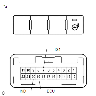
2. INSPECT NO. 2 COMBINATION SWITCH ASSEMBLY
| (a) Measure the voltage according to the value (s) in the table below. Standard Voltage:
HINT: As the circuit has a diode, perform the measurement in diode test mode, and do not mistake the polarity. |
|
(b) Measure the resistance according to the value (s) in the table below
Standard Resistance:
| Tester Connection | Switch Condition | Specified Condition |
|---|---|---|
| 7 (IG1) - 19 (ECU) | Steering heater switch is pushed | Below 1 Ω |
| Steering heater switch is not pushed | 10 kΩ or higher |
(c) Measure the voltage according to the value (s) in the table below.
(d) Measure the resistance according to the value (s) in the table below.
3. INSTALL NO. 2 COMBINATION SWITCH ASSEMBLY
Click here
READ NEXT:
 Precaution
PRECAUTION PRECAUTION FOR DISCONNECTING CABLE FROM NEGATIVE AUXILIARY BATTERY TERMINAL NOTICE:
After the power switch is turned off, there may be a waiting time before disconnecting the negative (-
Parts Location
PARTS LOCATION ILLUSTRATION *1 NO. 1 ENGINE ROOM RELAY BLOCK - IG2-MAIN RELAY - IG2-MAIN FUSE - STRG LOCK FUSE - - ILLUSTRATION *1 POWER SWITCH *2 INSTRUMENT PANEL JUNCTION BLOC
SEE MORE:
Poor Engine Power (P3190,P3191)
DESCRIPTION The ECM receives signals from the hybrid vehicle control ECU such as the requested engine torque, target engine speed and engine cranking status, and controls the engine output based on the target engine speed and requested torque. DTC No. Detection Item DTC Detection Condition
Dtc Check / Clear
DTC CHECK / CLEAR CHECK DTC (a) Connect the Techstream to the DLC3. (b) Turn the power switch on (IG). (c) Turn the Techstream on. (d) Enter the following menus: Powertrain / Radar Cruise1*1 or Radar Cruise2*2 / Trouble Codes. Powertrain > Radar Cruise1 > Trouble Codes Powertrain > Radar Cr
