Lexus NX: Steering Wheel does not Heat Up When Heated Steering Wheel Switch is Pressed
DESCRIPTION
Click here .gif)
WIRING DIAGRAM
Click here
CAUTION / NOTICE / HINT
HINT:
- Inspect the fuses for circuits related to this system before performing the following inspection procedure.
- The steering wheel heater unit is built into the steering wheel assembly which cannot be disassembled. Therefore, when the steering wheel heater unit has a malfunction, replace the steering wheel assembly.
PROCEDURE
| 1. | INSPECT STEERING WHEEL HEATER UNIT (THERMISTOR/HEATER/THERMOSTAT) |
| (a) Disconnect the B steering vibration and heater ECU connector. |
|
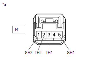
(b) Measure the resistance according to the value(s) in the table below.
Standard Resistance:
| Tester Connection | Condition | Specified Condition |
|---|---|---|
| B-3 (TH1) - B-2 (TH2) | 10 to 30°C (50 to 86°F) | 8.132 to 18.43 kΩ |
| B-5 (SH1) - B-1 (SH2) | 20°C (68°F) | 1.91 to 2.25 Ω |
| NG | .gif) | REPLACE STEERING WHEEL ASSEMBLY |
|
.gif)
| 2. | INSPECT SPIRAL WITH SENSOR CABLE SUB-ASSEMBLY |
(a) Check the connectors and cables of the spiral cable with sensor sub-assembly.
OK:
There are no defects such as scratches, cracks, dents or damage on the connectors or cables.
(b) Disconnect the I156 and z18 spiral cable with sensor sub-assembly connectors.
(c) Measure the resistance according to the value(s) in the table below.
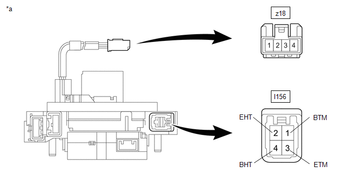
| *a | Component without harness connected (Spiral Cable with Sensor Sub-assembly) | - | - |
Standard Resistance:
| Tester Connection | Condition | Specified Condition |
|---|---|---|
| z18-2 - I156-1 (BTM) | Always | 3 Ω or less |
| z18-3 - I156-3 (ETM) | Always | 3 Ω or less |
| z18-1 - I156-2 (EHT) | Always | 0.02 to 0.28 Ω |
| z18-4 - I156-4 (BHT) | Always | 0.02 to 0.28 Ω |
| NG | | REPLACE SPIRAL WITH SENSOR CABLE SUB-ASSEMBLY |
|
| 3. | INSPECT NO. 2 COMBINATION SWITCH ASSEMBLY (STEERING HEATER SWITCH) |
(a) Remove the No. 2 combination switch assembly.
Click here
(b) Inspect the No. 2 combination switch assembly (steering heater switch).
Click here
| NG | | REPLACE NO. 2 COMBINATION SWITCH ASSEMBLY |
|
| 4. | CHECK STEERING HEATER RELAY |
| (a) Remove the STRG HTR relay from the No. 2 engine room relay block. |
|
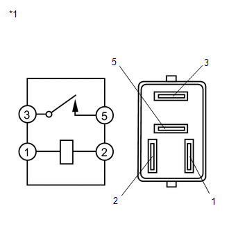
(b) Measure the resistance according to the value(s) in the table below.
Standard Resistance:
| Tester Connection | Condition | Specified Condition |
|---|---|---|
| 3 - 5 | Voltage is not applied between terminals 1 and 2 | 10 kΩ or higher |
| 3 - 5 | Voltage is applied between terminals 1 and 2 | Below 1 Ω |
| NG | | REPLACE STEERING HEATER RELAY |
|
| 5. | CHECK HARNESS AND CONNECTOR (NO. 2 COMBINATION SWITCH ASSEMBLY - SPIRAL WITH SENSOR CABLE SUB-ASSEMBLY) |
(a) Disconnect the I37 No. 2 combination switch assembly connector.
(b) Disconnect the I156 spiral with sensor cable sub-assembly connector.
(c) Measure the resistance according to the value(s) in the table below.
Standard Resistance:
| Tester Connection | Condition | Specified Condition |
|---|---|---|
| I37-16 (ECU) - I156-3 (ETM) | Always | Below 1 Ω |
| I37-9 (IND) - I156-1 (BTM) | Always | Below 1 Ω |
| I37-16 (ECU) or I156-3 (ETM) - Body ground | Always | 10 kΩ or higher |
| I37-9 (IND) or I156-1 (BTM) - Body ground | Always | 10 kΩ or higher |
| NG | | REPAIR OR REPLACE HARNESS OR CONNECTOR |
|
| 6. | CHECK HARNESS AND CONNECTOR (STRG HTR RELAY - SPIRAL WITH SENSOR CABLE SUB-ASSEMBLY) |
(a) Remove the STRG HTR relay from the No. 2 engine room relay block.
(b) Disconnect the I156 spiral with sensor cable sub-assembly connector.
(c) Measure the resistance according to the value(s) in the table below.
Standard Resistance:
| Tester Connection | Condition | Specified Condition |
|---|---|---|
| 5 - I156-4 (BHT) | Always | Below 1 Ω |
| 5 or I156-4 (BHT) - Body ground | Always | 10 kΩ or higher |
| NG | | REPAIR OR REPLACE HARNESS OR CONNECTOR |
|
| 7. | CHECK HARNESS AND CONNECTOR (NO. 2 COMBINATION SWITCH ASSEMBLY POWER SOURCE) |
| (a) Disconnect the I37 No. 2 combination switch assembly connector. |
|
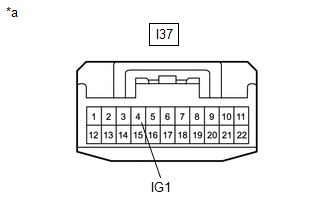
(b) Measure the voltage according to the value(s) in the table below.
Standard Voltage:
| Tester Connection | Switch Condition | Specified Condition |
|---|---|---|
| I37-4 (IG1) - Body ground | Power switch on (IG) | 11 to 14 V |
| NG | | REPAIR OR REPLACE HARNESS OR CONNECTOR |
|
| 8. | CHECK HARNESS AND CONNECTOR (STRG HTR RELAY POWER SOURCE) |
(a) Remove the STRG HTR relay from the No. 2 engine room relay block.
(b) Measure the voltage according to the value(s) in the table below.
Standard Voltage:
| Tester Connection | Condition | Specified Condition |
|---|---|---|
| 3 - Body ground | Always | 11 to 14 V |
| 1 - Body ground | Power switch on (IG) | 11 to 14 V |
(c) Measure the resistance according to the value(s) in the table below.
Standard Resistance:
| Tester Connection | Condition | Specified Condition |
|---|---|---|
| 2 - Body ground | Always | Below 1 Ω |
| NG | | REPAIR OR REPLACE HARNESS OR CONNECTOR |
|
| 9. | CHECK HARNESS AND CONNECTOR (SPIRAL WITH SENSOR CABLE SUB-ASSEMBLY BODY GROUND) |
(a) Disconnect the I156 spiral with sensor cable sub-assembly connector.
(b) Measure the resistance according to the value(s) in the table below.
Standard Resistance:
| Tester Connection | Condition | Specified Condition |
|---|---|---|
| I156-2 (EHT) - Body ground | Always | Below 1 Ω |
| OK | | REPLACE STEERING VIBRATION AND HEATER ECU |
| NG | | REPAIR OR REPLACE HARNESS OR CONNECTOR |
READ NEXT:
 Components
COMPONENTS ILLUSTRATION *1 DECK FLOOR BOX LH *2 REAR DECK FLOOR BOX *3 NO. 3 DECK BOARD SUB-ASSEMBLY *4 NEGATIVE AUXILIARY BATTERY TERMINAL N*m (kgf*cm, ft.*lbf): Specified
Installation
INSTALLATION PROCEDURE 1. INSTALL MULTIPLEX TILT AND TELESCOPIC ECU (a) Attach the claw and install the multiplex tilt and telescopic ECU to the bracket. (b) Install the bolt and multiplex tilt and te
SEE MORE:
Parts Location
PARTS LOCATION ILLUSTRATION *1 NO. 2 ENGINE ROOM RELAY BLOCK
- P/SEAT F/R FUSE
*2 INSTRUMENT PANEL JUNCTION BLOCK ASSEMBLY
- P/SEAT F/L FUSE
ILLUSTRATION *A for Driver Side - - *1 LUMBAR SUPPORT ADJUSTER ASSEMBLY LH *2 FRONT LUMBAR POWER SEAT SWITCH *
Operating Light Control Rheostat does not Change Light Brightness
DESCRIPTION The combination meter assembly receives signals from this circuit to adjust the illumination of the combination meter assembly. The combination meter assembly sets the illumination level based on the user operation of the light control rheostat switch in the trip switch. WIRING DIAGRAM
