- The power source mode changes to on (READY) even though the hybrid control system is not started.
- The power source mode does not change to on (READY) even though the hybrid control system is started.
Lexus NX: STSW Monitor Malfunction (B2275)
Lexus NX Service Manual / Vehicle Interior / Theft Deterrent / Keyless Entry / Smart Access System With Push-button Start (for Start Function) / STSW Monitor Malfunction (B2275)
DESCRIPTION
This DTC is stored when a malfunction is detected in the starter circuit inside the certification ECU (smart key ECU assembly).
| DTC No. | Detection Item | DTC Detection Condition | Trouble Area | Note |
|---|---|---|---|---|
| B2275 | STSW Monitor Malfunction | Certification ECU (smart key ECU assembly) internal HV activation request output circuit malfunction or external circuit malfunction (1-trip detection logic*) |
|
|
- *: Only detected while a malfunction is present and the power switch is on (IG).
| Vehicle Condition when Malfunction Detected | Fail-safe Function when Malfunction Detected |
|---|---|
| | - |
| DTC No. | Data List and Active Test |
|---|---|
| B2275 | Power Source Control
|
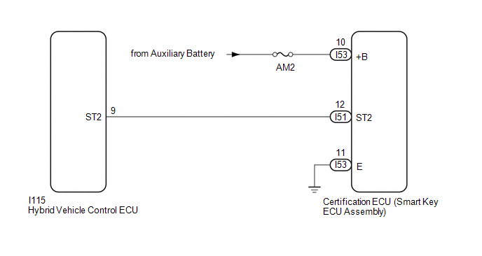
WIRING DIAGRAM
CAUTION / NOTICE / HINT
NOTICE:
- When using the Techstream with the power switch off, connect the Techstream to the DLC3 and turn a courtesy light switch on and off at intervals of 1.5 seconds or less until communication between the Techstream and the vehicle begins. Then select the vehicle type under manual mode and enter the following menus: Body Electrical / Smart Access. While using the Techstream, periodically turn a courtesy light switch on and off at intervals of 1.5 seconds or less to maintain communication between the Techstream and the vehicle.
-
The smart access system with push-button start (for Start Function) uses the LIN communication system and CAN communication system. Inspect the communication function by following How to Proceed with Troubleshooting. Troubleshoot the smart access system with push-button start (for Start Function) after confirming that the communication systems are functioning properly.
Click here
.gif)
-
Before replacing the certification ECU (smart key ECU assembly), refer to smart access system with push-button start (for Start Function) Precaution.
Click here
- Inspect the fuses of circuits related to this system before performing the following procedure.
- After repair, confirm that no DTCs are output by performing "DTC Output Confirmation Operation".
HINT:
When the cable is disconnected and reconnected to the negative (-) auxiliary battery terminal, the power source mode returns to the state it was in before the cable was disconnected.
PROCEDURE
| 1. | CHECK FOR DTC |
(a) Turn the power switch on (IG) and wait 25 seconds.
(b) Using the Techstream, check for DTCs.
Body Electrical > Power Source Control > Trouble CodesOK:
DTC B2285 is not output simultaneously.
| NG | .gif) | GO TO DTC B2285 |
|
.gif)
| 2. | CHECK HARNESS AND CONNECTOR (POWER SOURCE) |
Click here
| NG | | REPAIR OR REPLACE HARNESS OR CONNECTOR IN CIRCUIT CONNECTED TO POWER SOURCE |
|
| 3. | CHECK HARNESS AND CONNECTOR (GROUND) |
Click here
| NG | | REPAIR OR REPLACE HARNESS OR CONNECTOR |
|
| 4. | CHECK HARNESS AND CONNECTOR (CERTIFICATION ECU (SMART KEY ECU ASSEMBLY) - HYBRID VEHICLE CONTROL ECU) |
(a) Disconnect the I51 certification ECU (smart key ECU assembly) connector.
(b) Disconnect the I115 hybrid vehicle control ECU connector.
(c) Measure the resistance according to the value(s) in the table below.
Standard Resistance:
| Tester Connection | Condition | Specification Condition |
|---|---|---|
| I51-12 (ST2) - I115-9 (ST2) | Always | Below 1 Ω |
| I51-12 (ST2) or I115-9 (ST2) - Body ground | Always | 10 kΩ or higher |
| NG | | REPAIR OR REPLACE HARNESS OR CONNECTOR |
|
| 5. | CHECK CERTIFICATION ECU (SMART KEY ECU ASSEMBLY) |
(a) Reconnect the I51 certification ECU (smart key ECU assembly) connector.
(b) Reconnect the I115 hybrid vehicle control ECU connector.
(c) Measure the voltage according to the value(s) in the table below.
Standard Voltage:
| Tester Connection | Condition | Specification Condition |
|---|---|---|
| I51-12 (ST2) - Body ground | With the brake pedal depressed, the power switch is pressed and held → After approx. 3 sec. has elapsed, the power switch is released | 9 V or higher → 1 V or less |
| OK | | REPLACE HYBRID VEHICLE CONTROL ECU |
| NG | | REPLACE CERTIFICATION ECU (SMART KEY ECU ASSEMBLY) |
READ NEXT:
 Detecting Vehicle Submersion (B2277)
DESCRIPTION This DTC is stored when a malfunction in the water submersion detection circuit in the certification ECU (smart key ECU assembly) is detected. DTC No. Detection Item DTC Detection C
Vehicle Speed Signal Malfunction (B2282,B2283)
DESCRIPTION DTC B2282 is stored when the vehicle speed signal sent by the combination meter assembly via direct line and the vehicle speed signal sent via CAN communication do not match. DTC B2283 is
Steering Lock Position Signal Circuit Malfunction (B2285)
DESCRIPTION This DTC is stored when the steering lock position signal sent by the steering lock ECU (steering lock actuator assembly) via direct line and the steering lock position signal sent via LIN
SEE MORE:
Coolant
ReplacementREPLACEMENT PROCEDURE 1. DRAIN ENGINE COOLANT CAUTION: Do not remove the reservoir cap while the engine assembly and radiator assembly are still hot. Pressurized, hot engine coolant and steam may be released and cause serious burns. (a) Detach the 4 clips and remove the rear engine un
Open in IG Circuit (B242E)
DESCRIPTION This DTC is output when there is a problem in the power supply for the headlight ECU sub-assembly RH. The headlight ECU sub-assembly LH outputs DTC B242E. DTC No. Detection Item DTC Detection Condition Trouble Area B242E Open in IG Circuit IG circuit malfunction in the h
© 2016-2026 Copyright www.lexunx.com
