- When the signal sent via either direct line or CAN communication is malfunctioning and indicates that the vehicle speed is 0 km/h (0 mph), there is no effect on vehicle behavior.
- When the signal sent via either direct line or CAN communication is malfunctioning and indicates that the vehicle is moving, the power switch cannot be turned from on (IG) to off.
Lexus NX: Vehicle Speed Signal Malfunction (B2282,B2283)
Lexus NX Service Manual / Vehicle Interior / Theft Deterrent / Keyless Entry / Smart Access System With Push-button Start (for Start Function) / Vehicle Speed Signal Malfunction (B2282,B2283)
DESCRIPTION
DTC B2282 is stored when the vehicle speed signal sent by the combination meter assembly via direct line and the vehicle speed signal sent via CAN communication do not match.
DTC B2283 is stored when a malfunction in the vehicle speed sensor is detected.
| DTC No. | Detection Item | DTC Detection Condition | Trouble Area | Note |
|---|---|---|---|---|
| B2282 | Vehicle Speed Signal Malfunction | The vehicle speed signal sent by the combination meter assembly via direct line and the vehicle speed signal sent via CAN communication do not match. (1-trip detection logic*) |
|
|
| B2283 | Vehicle Speed Sensor Malfunction | Vehicle speed signal malfunction is detected (excessive deceleration is detected). (1-trip detection logic*) |
|
|
- *: Only detected while a malfunction is present and the power switch is on (IG).
| DTC No. | Vehicle Condition when Malfunction Detected | Fail-safe Function when Malfunction Detected |
|---|---|---|
| B2282 | | - |
| B2283 |
| Steering lock motor operation is prohibited. |
| DTC No. | Data List and Active Test |
|---|---|
| B2282 B2283 | Power Source Control
Combination Meter
|
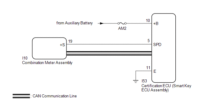
WIRING DIAGRAM
CAUTION / NOTICE / HINT
NOTICE:
- When using the Techstream with the power switch off, connect the Techstream to the DLC3 and turn a courtesy light switch on and off at intervals of 1.5 seconds or less until communication between the Techstream and the vehicle begins. Then select the vehicle type under manual mode and enter the following menus: Body Electrical / Smart Access. While using the Techstream, periodically turn a courtesy light switch on and off at intervals of 1.5 seconds or less to maintain communication between the Techstream and the vehicle.
-
The smart access system with push-button start (for Start Function) uses the LIN communication system and CAN communication system. Inspect the communication function by following How to Proceed with Troubleshooting. Troubleshoot the smart access system with push-button start (for Start Function) after confirming that the communication systems are functioning properly.
Click here
.gif)
- Inspect the fuses of circuits related to this system before performing the following procedure.
-
Before replacing the certification ECU (smart key ECU assembly), refer to the smart access system with push-button start (for Start Function) Precaution.
Click here
- After repair, confirm that no DTCs are output by performing "DTC Output Confirmation Operation".
HINT:
When the cable is disconnected and reconnected to the negative (-) auxiliary battery terminal, the power source mode returns to the state it was in before the cable was disconnected.
PROCEDURE
| 1. | READ VALUE USING TECHSTREAM (VEHICLE SPEED METER) |
(a) Connect the Techstream to the DLC3.
(b) Turn the power switch on (IG).
(c) Turn the Techstream on.
(d) Enter the following menus: Body Electrical / Combination Meter / Data List.
(e) Read the Data List according to the display on the Techstream.
Body Electrical > Combination Meter > Data List| Tester Display | Measurement Item | Range | Normal Condition | Diagnostic Note |
|---|---|---|---|---|
| Vehicle Speed Meter | Vehicle speed | Min.: 0, Max.: 255 | Almost same as actual vehicle speed (Speedometer tester) | - |
| Tester Display |
|---|
| Vehicle Speed Meter |
HINT:
Using a speedometer tester, check the actual vehicle speed and the vehicle speed displayed on the Techstream.
OK:
Vehicle speed displayed on the Techstream is almost the same as the actual vehicle speed measured using a speedometer tester.
| NG | .gif) | GO TO METER / GAUGE SYSTEM (Speedometer Malfunction) |
|
.gif)
| 2. | READ VALUE USING TECHSTREAM (VEHICLE SPEED SIGNAL) |
(a) Enter the following menus: Body Electrical / Power Source Control / Data List.
(b) Read the Data List according to the display on the Techstream.
Body Electrical > Power Source Control > Data List| Tester Display | Measurement Item | Range | Normal Condition | Diagnostic Note |
|---|---|---|---|---|
| Vehicle Speed Signal | Vehicle being driven or stopped | Stop or Run | Stop: Vehicle stopped Run: Vehicle being driven at 5 km/h (3 mph) or more | - |
| Tester Display |
|---|
| Vehicle Speed Signal |
OK:
The Techstream display changes correctly in response to the vehicle condition.
| OK | | GO TO METER / GAUGE SYSTEM (HOW TO PROCEED WITH TROUBLESHOOTING) |
|
| 3. | CHECK HARNESS AND CONNECTOR (POWER SOURCE) |
Click here
| NG | | REPAIR OR REPLACE HARNESS OR CONNECTOR IN CIRCUIT CONNECTED TO POWER SOURCE |
|
| 4. | CHECK HARNESS AND CONNECTOR (GROUND) |
Click here
| NG | | REPAIR OR REPLACE HARNESS OR CONNECTOR |
|
| 5. | CHECK HARNESS AND CONNECTOR (CERTIFICATION ECU (SMART KEY ECU ASSEMBLY) - COMBINATION METER ASSEMBLY) |
(a) Disconnect the I53 certification ECU (smart key ECU assembly) connector.
(b) Disconnect the I10 combination meter assembly connector.
(c) Measure the resistance according to the value(s) in the table below.
Standard Resistance:
| Tester Connection | Condition | Specified Condition |
|---|---|---|
| I53-5 (SPD) - I10-19 (+S) | Always | Below 1 Ω |
| I53-5 (SPD) or I10-19 (+S) - Body ground | Always | 10 kΩ or higher |
| NG | | REPAIR OR REPLACE HARNESS OR CONNECTOR |
|
| 6. | CHECK CERTIFICATION ECU (SMART KEY ECU ASSEMBLY) |
(a) Reconnect the I53 certification ECU (smart key ECU assembly) connector.
(b) Reconnect the I10 combination meter assembly connector.
(c) Using an oscilloscope, check the waveform.
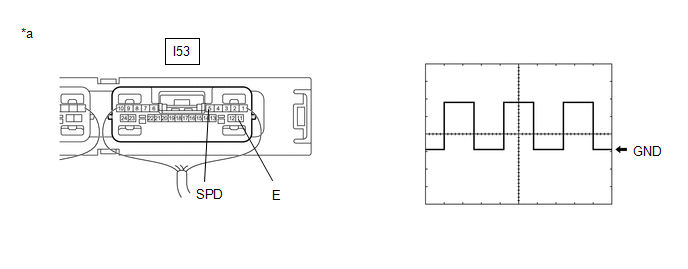
| *a | Component with harness connected (Certification ECU (Smart Key ECU Assembly)) | - | - |
Standard Frequency:
| Tester Connection | Condition | Tool Setting | Specified Condition |
|---|---|---|---|
| I53-5 (SPD) - I53-11 (E) | Vehicle being driven at approx. 5 km/h (3 mph) | 5 V/DIV., 200 ms./DIV. | Pulse generation |
HINT:
The wavelength becomes shorter as the vehicle speed increases.
| OK | | REPLACE CERTIFICATION ECU (SMART KEY ECU ASSEMBLY) |
| NG | | GO TO METER / GAUGE SYSTEM (Speed Signal Circuit) |
READ NEXT:
 Steering Lock Position Signal Circuit Malfunction (B2285)
DESCRIPTION This DTC is stored when the steering lock position signal sent by the steering lock ECU (steering lock actuator assembly) via direct line and the steering lock position signal sent via LIN
Lost Communication with Main Body ECU (U0140,U0142,U0155,U0293,U1117)
DESCRIPTION These DTCs are stored when there is a CAN communication error between the hybrid vehicle control ECU, certification ECU (smart key ECU assembly), ECM, main body ECU (multiplex network body
Power Source Mode does not Change to ON (IG)
DESCRIPTION If the power switch is pressed with the electrical key transmitter sub-assembly in the cabin, the certification ECU (smart key ECU assembly) receives a signal and changes the power source
SEE MORE:
Precaution
PRECAUTION CAUTION: Replace any faulty parts of the seat belt systems (outer belt, inner belt, bolts, nuts, adjustable shoulder anchor, tether anchor hardware and other related parts). When inspecting a vehicle that was in a collision, be sure to check all of the seat belt systems regardless of whet
Freeze Frame Data
FREEZE FRAME DATA FREEZE FRAME DATA NOTICE:
It is difficult to show the specified values (judgment values) clearly because freeze frame data values change significantly due to differences in measurement conditions, surroundings, or vehicle conditions. For this reason, there may be a problem even
© 2016-2026 Copyright www.lexunx.com
