Lexus NX: Terminals Of Ecu
TERMINALS OF ECU
CHECK HEADLIGHT ECU SUB-ASSEMBLY LH
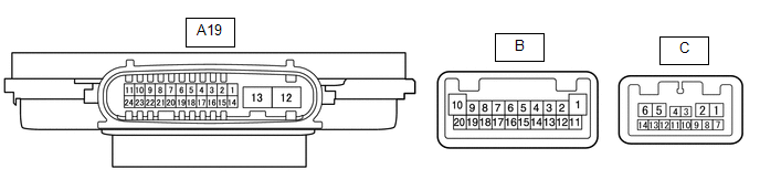
(a) Disconnect the A19 headlight sub-assembly LH connector.
(b) Measure the resistance and voltage according to the value(s) in the table below.
| Terminal No. (Symbol) | Wiring Color | Terminal Description | Condition | Specified Condition |
|---|---|---|---|---|
| A19-4 (IG) - Body ground | L - Body ground | Ignition power supply | Power switch off | Below 1 V |
| Power switch on (IG) | 11 to 14 V | |||
| A19-13 (ECUB) - Body ground | R - Body ground | Power supply | Power switch off | Below 1 V |
| Power switch on (IG) | 11 to 14 V | |||
| A19-12 (GND) - Body ground | W-B - Body ground | Ground | Always | Below 1 Ω |
(c) Reconnect the A19 headlight ECU sub-assembly LH connector.
HINT:
Since the headlight ECU sub-assembly LH uses waterproof connectors, the voltage, resistance and waveform cannot be checked directly. The voltage, resistance and waveform are indicated for reference only.
(d) Measure the voltage according to the value(s) in the table below.
| Terminal No. (Symbol) | Wiring Color | Terminal Description | Condition | Specified Condition |
|---|---|---|---|---|
| A19-16 (SBR) - A19-15 (SGR) | R - P | Rear height control sensor power supply | Power switch on (IG) | Approximately 5 V |
| A19-17 (SHRL) - A19-15 (SGR) | L - P | Rear height control sensor signal input | (No passengers, no luggage, vehicle not moving) | Approximately 2.5 V (vehicle level) (value decreases as the front of the vehicle is raised) |
CHECK HEADLIGHT ECU SUB-ASSEMBLY RH
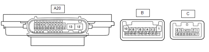
(a) Disconnect the A20 headlight ECU sub-assembly RH connector.
(b) Measure the resistance and voltage according to the value(s) in the table below.
| Terminal No. (Symbol) | Wiring Color | Terminal Description | Condition | Specified Condition |
|---|---|---|---|---|
| A20-4 (IG) - Body ground | G - Body ground | Ignition power supply | Power switch off | Below 1 V |
| Power switch on (IG) | 11 to 14 V | |||
| A20-13 (ECUB) - Body ground | B - Body ground | Power supply | Power switch off | Below 1 V |
| Power switch on (IG) | 11 to 14 V | |||
| A20-12 (GND) - Body ground | W-B - Body ground | Ground | Always | Below 1 Ω |
CHECK INSTRUMENT PANEL JUNCTION BLOCK ASSEMBLY, MAIN BODY ECU (MULTIPLEX NETWORK BODY ECU)
Click here .gif)
READ NEXT:
 Diagnosis System
DIAGNOSIS SYSTEM DESCRIPTION (a) Lighting system data and the Diagnostic Trouble Codes (DTCs) can be read from the Data Link Connector 3 (DLC3) of the vehicle. When the system seems to be malfunctioni
Dtc Check / Clear
DTC CHECK / CLEAR CHECK FOR DTC (a) Connect the Techstream to the DLC3. (b) Turn the power switch on (IG). (c) Turn the Techstream on. (d) Enter the following menus: Body Electrical / AFS / Trouble Co
Fail-safe Chart
FAIL-SAFE CHART FAIL-SAFE FUNCTION (a) Headlight ECU sub-assembly (1) The headlight ECU sub-assembly stops light operation if the following malfunctions are detected. Malfunction Multi-informatio
SEE MORE:
Diagnosis System
DIAGNOSIS SYSTEM DESCRIPTION The ECU stores DTCs when malfunctions occur. The diagnostic system allows for reading of the DTCs from the DLC3. Use the Techstream to check for malfunctions and perform repairs. CHECK DLC3 (a) Check the DLC3. Click here INSPECT AUXILIARY BATTERY VOLTAGE (a) Measure t
Disposal
DISPOSAL CAUTION / NOTICE / HINT HINT: The tire pressure warning valve and transmitter is powered by a lithium battery. When disposing of the tire pressure warning valve and transmitter, remove the battery and dispose of it properly. PROCEDURE 1. DISPOSE OF TIRE PRESSURE WARNING VALVE AND TRANSMITTE
