Lexus NX: Removal
REMOVAL
PROCEDURE
1. REMOVE DOOR SCUFF PLATE ASSEMBLY LH
Click here .gif)
2. REMOVE COWL SIDE TRIM BOARD LH
Click here
3. REMOVE CONSOLE ARMREST ASSEMBLY
Click here
4. REMOVE UPPER REAR CONSOLE PANEL
Click here
5. REMOVE UPPER NO. 1 CONSOLE PANEL GARNISH
Click here
6. REMOVE INSTRUMENT SIDE PANEL LH
Click here
7. REMOVE NO. 1 INSTRUMENT PANEL SAFETY PAD SUB-ASSEMBLY
Click here
8. REMOVE NO. 1 INSTRUMENT PANEL UNDER COVER SUB-ASSEMBLY
Click here
9. REMOVE LOWER NO. 1 INSTRUMENT PANEL FINISH PANEL
Click here
10. REMOVE COOLER THERMISTOR (ROOM TEMPERATURE SENSOR)
| (a) Detach the 2 claws. |
|
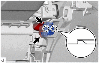
(b) Disconnect the connector.
(c) Disconnect the aspirator hose and remove the cooler thermistor (room temperature sensor).
READ NEXT:
 Inspection
INSPECTION PROCEDURE 1. INSPECT COOLER THERMISTOR (ROOM TEMPERATURE SENSOR) (a) Measure the resistance according to the value(s) in the table below. Standard Resistance: Tester Connection Con
Installation
INSTALLATION CAUTION / NOTICE / HINT HINT:
Use the same procedure for RHD and LHD vehicles.
The procedure listed below is for LHD vehicles.
PROCEDURE 1. INSTALL COOLER THERMISTOR (ROOM TEMPERA
Solar Sensor
ComponentsCOMPONENTS ILLUSTRATION *1 AUTOMATIC LIGHT CONTROL SENSOR (SOLAR SENSOR) *2 NO. 1 SPEAKER OPENING COVER ASSEMBLY RemovalREMOVAL PROCEDURE 1. REMOVE NO. 1 SPEAKER OPENING COVER
SEE MORE:
Hybrid Battery Pack State of Charge High (P0C30-390)
DESCRIPTION The hybrid vehicle control ECU monitors its internal operation and will store a DTC and perform fail-safe control if it detects the following malfunction. DTC No. Detection Item DTC Detection Condition Trouble Area MIL Warning Indicate P0C30-390 Hybrid Battery Pack Sta
Disassembly
DISASSEMBLY PROCEDURE 1. REMOVE CONSOLE COMPARTMENT DOOR SUB-ASSEMBLY (a) Remove the 4 screws and console compartment door sub-assembly. 2. REMOVE NO. 3 BOX PANEL (a) Detach the 2 clips and 2 claws, 3 guides and remove the No. 3 box panel. 3. REMOVE CONSOLE BOX PLATE (a
© 2016-2026 Copyright www.lexunx.com
