Lexus NX: System Diagram
Lexus NX Service Manual / Vehicle Interior / Meter / Gauge / Display / Meter / Gauge System / System Diagram
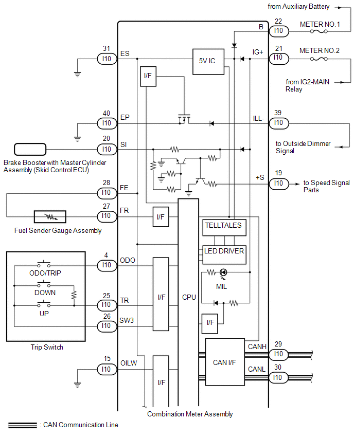
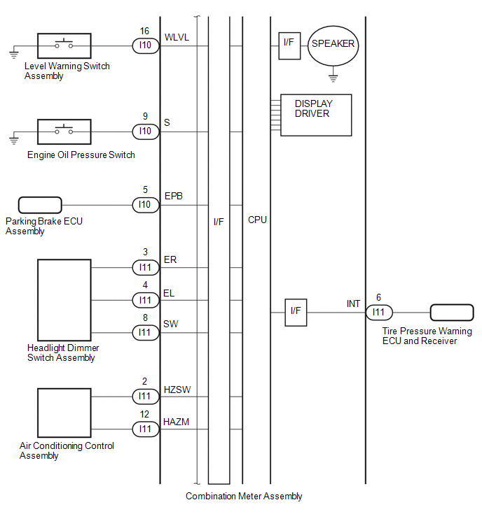
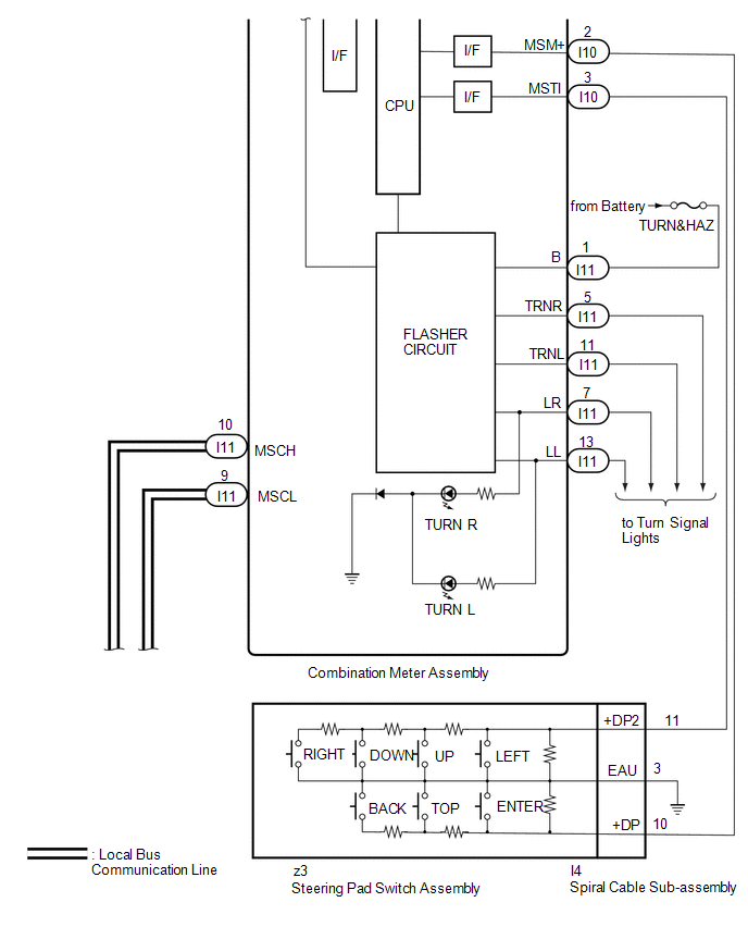
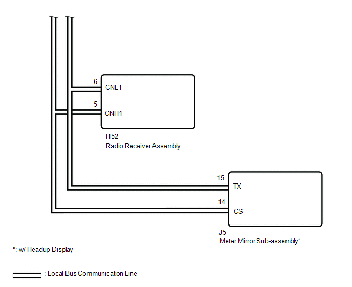
SYSTEM DIAGRAM
CAN SIGNAL
Click here .gif)
DIRECT LINE SIGNAL
READ NEXT:
 System Description
SYSTEM DESCRIPTION OUTLINE OF COMBINATION METER ASSEMBLY *a Indication Example *b Hybrid System Indicator or Tachometer *c Speedometer *d
Power Condition
ODO/TRIP Meter
How To Proceed With Troubleshooting
CAUTION / NOTICE / HINT HINT:
Use the following procedure to troubleshoot the meter / gauge system.
*: Use the Techstream.
PROCEDURE 1. VEHICLE BROUGHT TO WORKSHOP
NEXT
Operation Check
OPERATION CHECK INSPECT INDICATOR/WARNING LIGHT (a) Check the following indicators and warning lights. Indicator/Warning Light Switch Condition Specified Condition
*1: w/ Pre-collision Syst
SEE MORE:
Data List / Active Test
DATA LIST / ACTIVE TEST DATA LIST HINT: Using the Techstream to read the Data List allows the values or states of switches, sensors, actuators and other items to be read without removing any parts. This non-intrusive inspection can be very useful because intermittent conditions or signals may be dis
PBD Touch Sensor RH Circuit (B222B)
DESCRIPTION This DTC is output when the multiplex network door ECU detects a power back door sensor assembly RH touch sensor malfunction. DTC No. Detection Item DTC Detection Condition Trouble Area B222B PBD Touch Sensor RH Circuit Multiplex network door ECU detects power back door
© 2016-2026 Copyright www.lexunx.com
