- Transponder key amplifier
Lexus NX: System Diagram
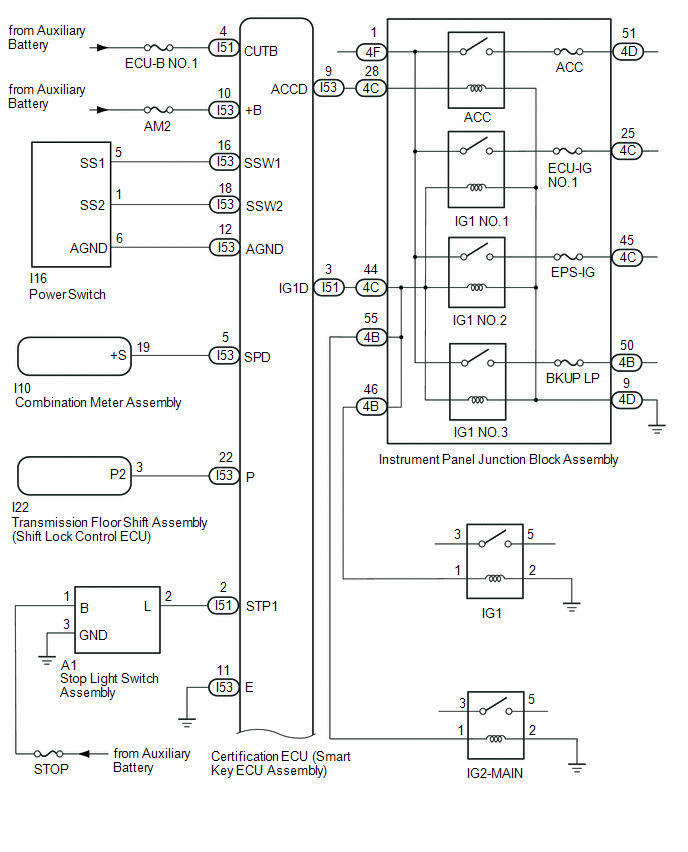
SYSTEM DIAGRAM
| Component | Outline |
|---|---|
| Power switch |
|
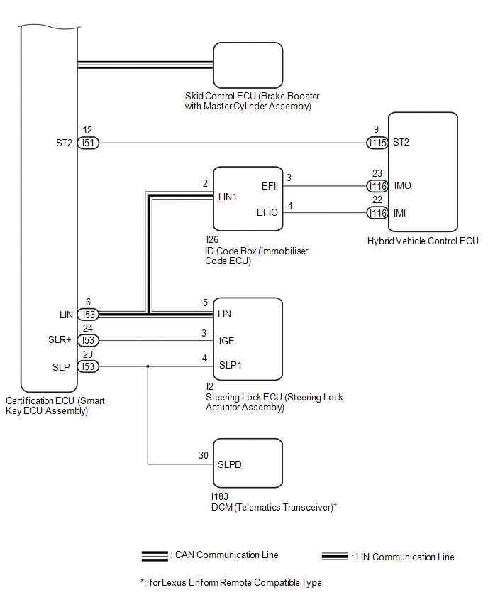
| Certification ECU (smart key ECU assembly) |
|
| ID code box (immobiliser code ECU) |
|
| Steering lock ECU (steering lock actuator assembly) |
|
| Combination meter assembly |
|
| IG, ACC relay | Turns on/off according to the certification ECU (smart key ECU assembly) and provides power to each system. |
| Stop light switch assembly | Detects that the brake pedal has been depressed (switch is on) and outputs a signal to the certification ECU (smart key ECU assembly). |
| Sends the request code from the certification ECU (smart key ECU assembly) and forms the vehicle interior detection area. |
| Door control receiver | Receives the smart access system with push-button start code/wireless code sent from the electrical key transmitter sub-assembly and sends it to the certification ECU (smart key ECU assembly). |
| Electrical key transmitter sub-assembly | Sends the ID code upon receiving a request signal. |
READ NEXT:
 System Description
SYSTEM DESCRIPTION SYSTEM FUNCTION Function Outline Push-button start function When the electrical key transmitter sub-assembly is brought into the vehicle and verified, this function chang
How To Proceed With Troubleshooting
CAUTION / NOTICE / HINT HINT:
Use these procedures to troubleshoot the smart access system with push-button start (for start function).
*: Use the Techstream.
PROCEDURE 1. VEHICLE BROUGH
Operation Check
OPERATION CHECK OPERATION DESCRIPTION NOTICE: Make sure that the smart access system with push-button start (for Start Function) has not been canceled before performing this inspection. Click here (
SEE MORE:
Control Module Communication Bus "A" Off (U0073,U0155)
DESCRIPTION These DTCs are stored when the clearance warning ECU assembly cannot receive and recognize several signals via the CAN communication line. DTC No. Detection Item DTC Detection Condition Trouble Area U0073 Control Module Communication Bus "A" Off Control module communicat
Freeze Frame Data
FREEZE FRAME DATA FREEZE FRAME DATA (a) Whenever an ASC system DTC is stored, the stereo component equalizer assembly stores the current vehicle state as freeze frame data. CHECK FREEZE FRAME DATA (a) Connect the Techstream to the DLC3. (b) Turn the power switch on (IG). (c) Turn the Techstream on.
© 2016-2026 Copyright www.lexunx.com
