Lexus NX: Operation Check
OPERATION CHECK
OPERATION DESCRIPTION
NOTICE:
Make sure that the smart access system with push-button start (for Start Function) has not been canceled before performing this inspection.
Click here .gif)
(a) Push-button start function:
(1) When the electrical key transmitter sub-assembly is in a detection area inside the vehicle and the brake pedal is depressed, the hybrid control system is started by pressing the power switch.
(2) When the electrical key transmitter sub-assembly is in a detection area inside the vehicle and the brake pedal is not depressed, the power source mode is changed by pressing the power switch. The power source mode changes in the following order every time the power switch is pressed: off → on (ACC) → on (IG) → off.
(3) After getting into the vehicle while carrying the electrical key transmitter sub-assembly when the power switch is off, if the power switch is pressed while not depressing the brake pedal, the power source mode changes to on (ACC) and "ACCESSORY" is displayed on the multi-information display.
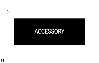
| *a | "ACCESSORY" Display |
(4) After getting into the vehicle while carrying the electrical key transmitter sub-assembly when the power switch is off, if the power switch is pressed 2 times without depressing the brake pedal, the power source mode changes to on (IG) and "IGNITION ON" is displayed on the multi-information display.
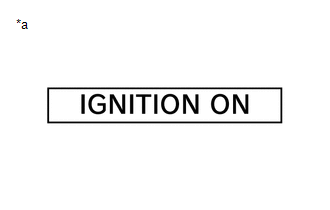
| *a | "IGNITION ON" Display |
(5) After getting into the vehicle while carrying the electrical key transmitter sub-assembly when the power switch is off, if the brake pedal is depressed while the shift lever is in P, the smart warning light is displayed on the multi-information display.
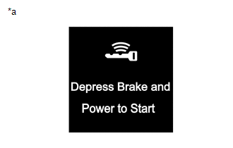
| *a | Smart Warning Light Display |
(6) The hybrid control system will start if the power switch is pressed when the smart warning light is displayed.
(b) Changing the power source mode when the electrical key transmitter sub-assembly does not operate correctly due to wave interference or transmitter battery depletion:
(1) Unlock the door using the built-in mechanical key and get into the vehicle while carrying the electrical key transmitter sub-assembly.
(2) While depressing the brake pedal and facing the logo side of the electrical key transmitter sub-assembly towards the power switch, hold the electrical key transmitter sub-assembly near the power switch.
(3) A buzzer in the combination meter assembly will sound and the power source mode changes to on (IG) and "IGNITION ON" is displayed on the multi-information display.
| *a | "IGNITION ON" Display |
(4) Pressing the power switch without depressing the brake pedal turns the power source mode from on (IG) to off.
(c) Starting the hybrid control system when the electrical key transmitter sub-assembly does not operate correctly due to wave interference or transmitter battery depletion:
(1) Unlock the door using the built-in mechanical key and get into the vehicle while carrying the electrical key transmitter sub-assembly.
(2) While depressing the brake pedal with the shift lever in P and facing the logo side of the electrical key transmitter sub-assembly towards the power switch, hold the electrical key transmitter sub-assembly near the power switch.
(3) A buzzer in the combination meter assembly will sound, the power source mode changes to on (IG) and the smart warning light will be displayed on the multi-information display.
| *a | Smart Warning Light Display |
(4) Press the power switch with the brake pedal depressed to start the hybrid control system.
CHECK PUSH-BUTTON START FUNCTION
(a) Check the push-button start function:
(1) Get into the vehicle while carrying the electrical key transmitter sub-assembly with the power switch off. With the shift lever in P, check that the smart warning light is displayed when the brake pedal is depressed. Check that the hybrid control system starts when the power switch is pressed after the smart warning light is displayed on the multi-information display.
| *a | Smart Warning Light Display |
(2) While the brake pedal is released and the electrical key transmitter sub-assembly is being carried, check that the power source mode changes in the following order when the power switch is pressed: off → on (ACC) → on (IG) → off.
HINT:
When the power switch is pressed with the power switch on (IG) and the shift lever not in P, the power source mode does not change to off, but changes to on (ACC).
(3) With the shift lever in P, check that the steering lock operates when a door is opened.
HINT:
When the power switch is pressed after the vehicle is stopped, the hybrid control system stops and all the power turns off. However, if the shift lever is not in P when the power switch is pressed with the vehicle stopped, the power source mode does not change to off, but changes to on (ACC).
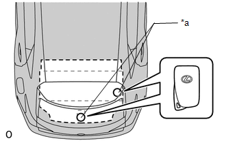
(4) Check the push-button start function operation range for the front side. Place the electrical key transmitter sub-assembly at either inspection point so that it is facing the direction shown in the illustration, and then check that the hybrid control system can be started.
NOTICE:
Even if the electrical key transmitter sub-assembly is in a vehicle interior key detection area, the electrical key transmitter sub-assembly may not be properly detected if the electrical key transmitter sub-assembly is on the instrument panel, in the glove box or on the floor.
.png)
| *a | Inspection Point |
HINT:
- Communication may not be possible if the electrical key transmitter sub-assembly is within 0.2 m (0.656 ft.) of the shift lever.
- Perform this inspection for both inspection points.
(5) Check the push-button start function operation range for the rear side. Place the electrical key transmitter sub-assembly at either inspection point so that it is facing the direction shown in the illustration, and then check that the hybrid control system can be started.
NOTICE:
Even if the electrical key transmitter sub-assembly is in a vehicle interior key detection area, the electrical key transmitter sub-assembly may not be properly detected if the electrical key transmitter sub-assembly is on the instrument panel, in the glove box or on the floor.
.png)
| *a | Inspection Point |
HINT:
- Communication may not be possible if the electrical key transmitter sub-assembly is within 0.2 m (0.656 ft.) of the center of the rear seat.
- Perform this inspection for both inspection points.
(6) Check the push-button start function operation range for the luggage side. Place the electrical key transmitter sub-assembly at either inspection point so that it is facing the direction shown in the illustration, and then check that the hybrid control system can be started.
NOTICE:
Even if the electrical key transmitter sub-assembly is in a vehicle interior key detection area, the electrical key transmitter sub-assembly may not be properly detected if the electrical key transmitter sub-assembly is on the instrument panel, in the glove box or on the floor.
HINT:
- Communication may not be possible if the electrical key transmitter sub-assembly is within 0.2 m (0.656 ft.) of the center of the rear seat.
- Perform this inspection for both inspection points.
| *a | Inspection Point |
CHECK TRANSMITTER BATTERY SAVING FUNCTION
(a) Check the transmitter battery saving mode function:
(1) Press the unlock switch of the electrical key transmitter sub-assembly twice while pressing the lock switch and check that the electrical key transmitter sub-assembly LED blinks 4 times and enters transmitter battery saving mode.
(2) Check that the smart access system with push-button start does not operate while in transmitter battery saving mode.
HINT:
To cancel transmitter battery saving mode, press a switch of the electrical key transmitter sub-assembly.
CHECK POWER SOURCE MODE CHANGING FUNCTION
(a) Check the power switch.
(1) Check that the power source mode changes according to the chart below.
| Shift Position | Brake Pedal | Power Source Mode when Power Switch Pressed |
|---|---|---|
| P | Released | Off → on (ACC) → on (IG) → off |
| P | Released | On (READY) → off |
| P | Released | On (ACC)* → on (IG) |
| P | Depressed | Off → on (READY) |
| P | Depressed | On (ACC) → on (READY) |
| P | Depressed | On (IG) → on (READY) |
| P | Depressed | On (READY) → off |
| P | Depressed | On (ACC)* → on (READY) |
| Not P | Released | Off → on (ACC) → on (IG) (after power source mode changes to on (IG), power source mode changes between on (IG) and on (ACC) every time power switch is pressed) |
| Not P | Released | On (READY) → on (ACC) |
| Not P | Depressed | Off → on (IG) |
| Not P | Depressed | On (ACC) → on (IG) |
| Not P | Depressed | On (READY) → on (ACC) |
HINT:
*: This situation is only applicable when the power source mode has changed from on (IG) to on (ACC). (Excluding an emergency stop by pressing the power switch 3 times quickly or pressing and holding the power switch for 2 seconds or more.)
CHECK POWER SOURCE MODE INDICATION
(a) Check the smart warning light .
Multi-information Display Inspection| Power Source Mode | Multi-information Display |
|---|---|
| Off (Excluding conditions in which the hybrid control system can be started) | Off |
| On (ACC) (Excluding conditions in which the hybrid control system can be started) | "ACCESSORY" displayed |
| On (IG) (Excluding conditions in which the hybrid control system can be started) | "IGNITION ON" displayed |
| Conditions in which hybrid control system can be started*1 | Smart Warning Light displayed |
| Hybrid control system started | Off |
HINT:
*1: Indicates the conditions in which the hybrid control system can be started by pressing the power switch while the following condition is met:
-
Condition
All of the following conditions are met:
- The power source mode was changed from on (IG) to off.
- Key verification is OK*2 or immobiliser is unset (power switch is on (ACC) or on (IG)).
- The power switch is not on (READY).
- The stop light switch is on.
- The shift lever is in P.
*2: When the electrical key transmitter sub-assembly is in the cabin, the ID code sent as a result of communication between the electrical key transmitter sub-assembly and certification ECU (smart key ECU assembly) and the ID code calculated by the certification ECU (smart key ECU assembly) are compared. If the ID codes match each other, the vehicle recognizes that the electrical key transmitter sub-assembly is in the cabin.
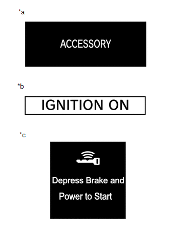
| *a | "ACCESSORY" Display |
| *b | "IGNITION ON" Display |
| *c | Smart Warning Light Display |
READ NEXT:
 Customize Parameters
CUSTOMIZE PARAMETERS CUSTOMIZE SMART ACCESS SYSTEM WITH PUSH-BUTTON START (for Start Function) HINT: The following items can be customized. NOTICE:
When the customer requests a change in a function
Problem Symptoms Table
PROBLEM SYMPTOMS TABLE HINT:
Use the table below to help determine the cause of problem symptoms. If multiple suspected areas are listed, the potential causes of the symptoms are listed in order of
Terminals Of Ecu
TERMINALS OF ECU CHECK CERTIFICATION ECU (SMART KEY ECU ASSEMBLY) (a) Disconnect the I51 and I53 certification ECU (smart key ECU assembly) connectors. (b) Measure the voltage and resistance accordin
SEE MORE:
Generator Control Module (P0A1A-166)
DESCRIPTION The MG ECU, which is built into the inverter with converter assembly, monitors its internal operation and will store DTCs if the system is malfunctioning. If any of the following DTCs are output, replace the inverter with converter assembly. DTC No. Detection Item DTC Detection Co
System Description
SYSTEM DESCRIPTION POWER MIRROR CONTROL SYSTEM DESCRIPTION (a) This system has the following functions: power retract function, auto power retract function, electrical remote control function, reverse shift-linked function, memory function, automatic glare-resistant EC mirror function and mirror hea
