.gif)
.png)
.png)
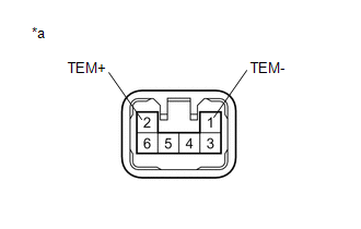
- 12 V battery positive (+) lead → Terminal 2 (TEM+)
- 12 V battery negative (-) lead → Terminal 1 (TEM-)
Lexus NX: Telescopic Position Sensor or Telescopic Motor Circuit Malfunction (B2611)
Lexus NX Service Manual / Steering / Steering Column / Power Tilt And Power Telescopic Steering Column System / Telescopic Position Sensor or Telescopic Motor Circuit Malfunction (B2611)
DESCRIPTION
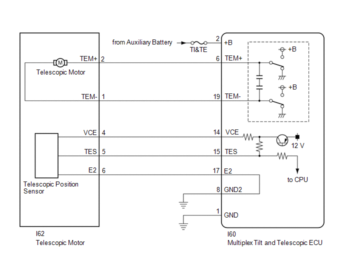
The telescopic motor is operated by the power source voltage supplied from the multiplex tilt and telescopic ECU and slides the steering column forward and backward. The telescopic position sensor (Hall IC) in the telescopic motor detects the sliding position of the steering column in the forward and backward directions and sends a signal to the multiplex tilt and telescopic ECU based on that sliding amount.
| DTC No. | Detection Item | DTC Detection Condition | Trouble Area |
|---|---|---|---|
| B2611 | Telescopic Position Sensor or Telescopic Motor Circuit Malfunction | Telescopic operation stops within the operation range while operating. |
|
WIRING DIAGRAM
CAUTION / NOTICE / HINT
NOTICE:
-
If the electric power steering column sub-assembly is replaced, perform actuator angle neutral point calibration.
Click here
.gif)
- Inspect the fuses for circuits related to this system before performing the following inspection procedure.
PROCEDURE
| 1. | PERFORM ACTIVE TEST USING TECHSTREAM (TILT OPERATION) |
(a) Turn the power switch off.
(b) Connect the Techstream to the DLC3.
(c) Turn the power switch on (IG).
(d) Turn the Techstream on.
(e) Check that the steering column contracts and extends.
(f) Enter the following menus: Body Electrical / Tilt & Telescopic / Active Test.
Body Electrical > Tilt&Telescopic > Active Test| Tester Display | Measurement Item | Control Range | Diagnostic Note |
|---|---|---|---|
| Telesco Operation | Telesco Operation | Long/Short | - |
| Tester Display |
|---|
| Telesco Operation |
OK:
The steering column contracts and extends.
| NG | .gif) | GO TO STEP 6 |
|
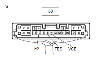
| 2. | CHECK HARNESS AND CONNECTOR (MULTIPLEX TILT AND TELESCOPIC ECU - TELESCOPIC POSITION SENSOR) |
(a) Disconnect the I60 multiplex tilt and telescopic ECU connector.
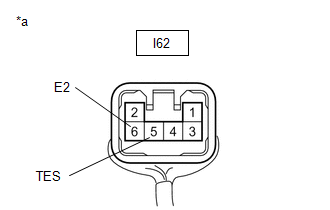
(b) Disconnect the I62 telescopic motor connector.
(c) Measure the resistance according to the value(s) in the table below.
Standard Resistance:
| Tester Connection | Condition | Specified Condition |
|---|---|---|
| I60-14 (VCE) - I62-4 (VCE) | Always | Below 1 Ω |
| I60-15 (TES) - I62-5 (TES) | Always | Below 1 Ω |
| I60-17 (E2) - I62-6 (E2) | Always | Below 1 Ω |
| I60-14 (VCE) - Body ground | Always | 10 kΩ or higher |
| I60-15 (TES) - Body ground | Always | 10 kΩ or higher |
| I60-17 (E2) - Body ground | Always | 10 kΩ or higher |
| NG | | REPAIR OR REPLACE HARNESS OR CONNECTOR |
|
| 3. | CHECK HARNESS AND CONNECTOR (MULTIPLEX TILT AND TELESCOPIC ECU - BODY GROUND) |
| (a) Disconnect the I60 multiplex tilt and telescopic ECU connector. |
|
(b) Measure the resistance according to the value(s) in the table below.
Standard Resistance:
| Tester Connection | Condition | Specified Condition |
|---|---|---|
| I60-1 (GND) - Body ground | Always | Below 1 Ω |
| I60-8 (GND2) - Body ground | Always | Below 1 Ω |
| NG | | REPAIR OR REPLACE HARNESS OR CONNECTOR |
|
| 4. | CHECK MULTIPLEX TILT AND TELESCOPIC ECU (VCE, TES TERMINAL VOLTAGE) |
| (a) Disconnect the I62 telescopic motor connector. |
|
(b) Reconnect the I60 multiplex tilt and telescopic ECU connector.
(c) Measure the voltage according to the value(s) in the table below.
Standard Voltage:
| Tester Connection | Condition | Specified Condition |
|---|---|---|
| I60-14 (VCE) - I60-17 (E2) | Power switch on (IG) | 8 to 14 V |
| I60-15 (TES) - I60-17 (E2) | Power switch on (IG) | 8 to 14 V |
| NG | | REPLACE MULTIPLEX TILT AND TELESCOPIC ECU |
|
| 5. | CHECK TELESCOPIC POSITION SENSOR |
| (a) Reconnect the I60 multiplex tilt and telescopic ECU connector. |
|
(b) Reconnect the I62 telescopic motor connector.
(c) Measure the voltage according to the value(s) in the table below.
Standard Voltage:
| Tester Connection | Condition | Specified Condition |
|---|---|---|
| I62-5 (TES) - I62-6 (E2) | Steering column contracting or extending | Pulse generation High: 8 to 14 V Low: Below 1 V |
| OK | | REPLACE MULTIPLEX TILT AND TELESCOPIC ECU |
| NG | | REPLACE ELECTRIC POWER STEERING COLUMN SUB-ASSEMBLY |
| 6. | CHECK HARNESS AND CONNECTOR (MULTIPLEX TILT AND TELESCOPIC ECU - AUXILIARY BATTERY) |
(a) Disconnect the I60 multiplex tilt and telescopic ECU connector.
| (b) Measure the voltage according to the value(s) in the table below. Standard Voltage:
|
|
| NG | | REPAIR OR REPLACE HARNESS OR CONNECTOR |
|
| 7. | CHECK HARNESS AND CONNECTOR (MULTIPLEX TILT AND TELESCOPIC ECU - BODY GROUND) |
| (a) Disconnect the I60 multiplex tilt and telescopic ECU connector. |
|
(b) Measure the resistance according to the value(s) in the table below.
Standard Resistance:
| Tester Connection | Condition | Specified Condition |
|---|---|---|
| I60-1 (GND) - Body ground | Always | Below 1 Ω |
| I60-8 (GND2) - Body ground | Always | Below 1 Ω |
| NG | | REPAIR OR REPLACE HARNESS OR CONNECTOR |
|
| 8. | CHECK HARNESS AND CONNECTOR (MULTIPLEX TILT AND TELESCOPIC ECU - TELESCOPIC MOTOR) |
(a) Disconnect the I60 multiplex tilt and telescopic ECU connector.
(b) Disconnect the I62 telescopic motor connector.
(c) Measure the resistance according to the value(s) in the table below.
Standard Resistance:
| Tester Connection | Condition | Specified Condition |
|---|---|---|
| I60-6 (TEM+) - I62-2 (TEM+) | Always | Below 1 Ω |
| I60-19 (TEM-) - I62-1 (TEM-) | Always | Below 1 Ω |
| I60-6 (TEM+) - Body ground | Always | 10 kΩ or higher |
| I60-19 (TEM-) - Body ground | Always | 10 kΩ or higher |
| NG | | REPAIR OR REPLACE HARNESS OR CONNECTOR |
|
| 9. | CHECK TELESCOPIC MOTOR |
| (a) Apply 12 V battery voltage to the telescopic motor connector. Then check the steering column telescopic operation. OK:
|
|
| OK | | REPLACE MULTIPLEX TILT AND TELESCOPIC ECU |
| NG | | REPLACE ELECTRIC POWER STEERING COLUMN SUB-ASSEMBLY |
READ NEXT:
 ECU Power Source Circuit Malfunction (B2620)
DESCRIPTION The ECU power source circuit supplies positive (+) voltage to the multiplex tilt and telescopic ECU. DTC No. Detection Item DTC Detection Condition Trouble Area B2620 ECU Po
Vehicles Speed Malfunction (B2624)
DESCRIPTION The multiplex tilt and telescopic ECU forms a network with the ECUs of other systems via CAN communication. Each ECU informs the other ECUs that it is connected to the network by sending a
Lost Communication with Main Body ECU (U0142,U0208)
DESCRIPTION The multiplex tilt and telescopic ECU receives signals from the main body ECU (multiplex network body ECU) and front power seat switch via CAN communication. DTC No. Detection Item
SEE MORE:
How To Proceed With Troubleshooting
CAUTION / NOTICE / HINT HINT:
Use the following procedure to troubleshoot the occupant classification system.
*: Use the Techstream.
PROCEDURE 1. VEHICLE BROUGHT TO WORKSHOP
NEXT 2. CUSTOMER PROBLEM ANALYSIS (a) Confirm problem symptoms. Click here
System Description
SYSTEM DESCRIPTION GENERAL (a) The air conditioning system has the following controls. Control Outline Neural Network Control This control is capable of performing complex control by artificially simulating the information processing method of the nervous system of living organisms in ord
© 2016-2026 Copyright www.lexunx.com
