Lexus NX: ECU Power Source Circuit Malfunction (B2620)
DESCRIPTION
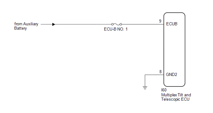
The ECU power source circuit supplies positive (+) voltage to the multiplex tilt and telescopic ECU.
| DTC No. | Detection Item | DTC Detection Condition | Trouble Area |
|---|---|---|---|
| B2620 | ECU Power Source Circuit Malfunction | The voltage of the ECU power source drops to 8 V or less and this condition continues for 10 seconds or more. |
|
WIRING DIAGRAM
CAUTION / NOTICE / HINT
NOTICE:
Inspect the fuses for circuits related to this system before performing the following procedure.
PROCEDURE
| 1. | CHECK HARNESS AND CONNECTOR (MULTIPLEX TILT AND TELESCOPIC ECU - AUXILIARY BATTERY) |
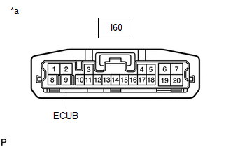
| (a) Disconnect the I60 multiplex tilt and telescopic ECU connector. |
|
(b) Measure the voltage according to the value(s) in the table below.
Standard Voltage:
| Tester Connection | Condition | Specified Condition |
|---|---|---|
| I60-9 (ECUB) - Body ground | Always | 11 to 14 V |
| NG | .gif) | REPAIR OR REPLACE HARNESS OR CONNECTOR |
|
.gif)
| 2. | CHECK HARNESS AND CONNECTOR (MULTIPLEX TILT AND TELESCOPIC ECU - BODY GROUND) |
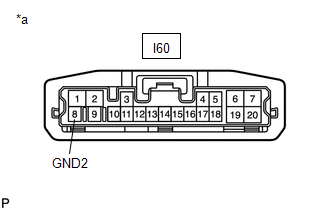
| (a) Disconnect the I60 multiplex tilt and telescopic ECU connector. |
|
(b) Measure the resistance according to the value(s) in the table below.
Standard Resistance:
| Tester Connection | Condition | Specified Condition |
|---|---|---|
| I60-8 (GND2) - Body ground | Always | Below 1 Ω |
| OK | | REPLACE MULTIPLEX TILT AND TELESCOPIC ECU |
.gif)
| NG | | REPAIR OR REPLACE HARNESS OR CONNECTOR |
READ NEXT:
 Vehicles Speed Malfunction (B2624)
DESCRIPTION The multiplex tilt and telescopic ECU forms a network with the ECUs of other systems via CAN communication. Each ECU informs the other ECUs that it is connected to the network by sending a
Lost Communication with Main Body ECU (U0142,U0208)
DESCRIPTION The multiplex tilt and telescopic ECU receives signals from the main body ECU (multiplex network body ECU) and front power seat switch via CAN communication. DTC No. Detection Item
Actuator Power Source Circuit
DESCRIPTION This is the power source for the power tilt and power telescopic steering column system. WIRING DIAGRAM CAUTION / NOTICE / HINT NOTICE: Inspect the fuses for circuits related to this syst
SEE MORE:
Components
COMPONENTS ILLUSTRATION *1 CRUISE CONTROL MAIN SWITCH *2 STEERING PAD SWITCH ASSEMBLY
Switch Lights of Remote Touch do not Illuminate
DESCRIPTION Power is supplied to the remote touch illumination when the light control switch is in the tail or head position. WIRING DIAGRAM CAUTION / NOTICE / HINT NOTICE: Inspect the fuse for circuits related to this system before performing the following procedure. PROCEDURE 1. CONFIRM SYM
