Lexus NX: Freeze Frame Data
FREEZE FRAME DATA
DESCRIPTION
The ECM records vehicle and driving condition information as freeze frame data the moment a DTC is stored. When troubleshooting, freeze frame data can be helpful in determining whether the vehicle was moving or stationary, whether the engine was warmed up or not, whether the air fuel ratio was lean or rich, as well as other data recorded at the time of a malfunction.
HINT:
If it is impossible to replicate the problem even though a DTC is detected, confirm the freeze frame data.
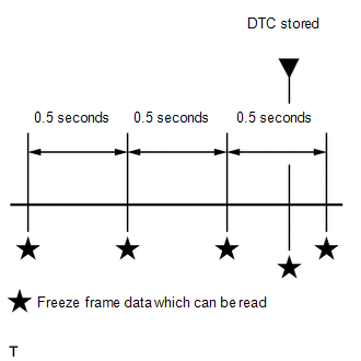
The ECM records engine conditions in the form of freeze frame data every 0.5 seconds. Using the Techstream, 5 separate sets of freeze frame data can be checked.
- 3 data sets before the DTC was stored.
- 1 data set when the DTC was stored.
- 1 data set after the DTC was stored.
These data sets can be used to simulate the condition of the vehicle around the time of the occurrence the malfunction. The data may assist in identifying the cause of the malfunction, and judging whether it was temporary or not.
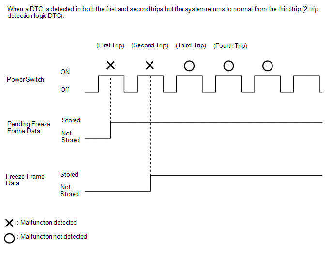
PENDING FREEZE FRAME DATA
HINT:
Pending freeze frame data is stored when a 2 trip DTC is first detected during the first trip.
(a) Connect the Techstream to the DLC3.
(b) Turn the power switch on (IG).
(c) Turn the Techstream on.
(d) Enter the following menus: Powertrain / Engine and ECT / Trouble Codes.
Powertrain > Engine and ECT > Trouble Codes(e) Select a DTC in order to display its pending freeze frame data.
HINT:
-
Pending freeze frame data is cleared when any of the following occurs.
- Using the Techstream, the DTCs cleared.
- The cable is disconnected from the negative (-) auxiliary battery terminal.
- 40 trips with the engine fully warmed up have been performed after returning to normal. (Pending freeze frame data will not be cleared by only returning the system to normal.)
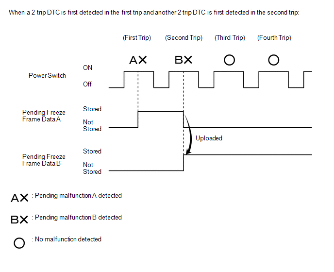
- With previous pending freeze frame data stored, if pending freeze frame data is newly stored when a 2 trip DTC is detected in the first trip, the old freeze frame data will be replaced with the new data of the newly detected DTC in the next trip.
LIST OF FREEZE FRAME DATA
Powertrain > Engine and ECT| Tester Display |
|---|
| Vehicle Speed |
| Engine Speed |
| Calculate Load |
| Vehicle Load |
| MAF |
| Atmosphere Pressure |
| MAP |
| Coolant Temp |
| Intake Air |
| Ambient Temperature |
| Engine Run Time |
| Initial Engine Coolant Temp |
| Coolant Temp Variation after Waterpump Start |
| Initial Intake Air Temp |
| Intake Air Temp Variation after Engine Start |
| Battery Voltage |
| Throttle Sensor Volt % |
| Throttle Sensor #2 Volt % |
| Throttle Sensor Position |
| Throttle Motor DUTY |
| Throttle Position |
| ISC Flow |
| ISC Position |
| ISC Feedback Value |
| ISC Learning Value |
| Electric Load Feedback Val |
| Air Conditioner FB Val |
| Low Revolution Control |
| Deposit Loss Flow |
| Fuel Pump Duty |
| Injector (Port) |
| Injection Volum (Cylinder1) |
| Vacuum Pump |
| Current Fuel Type |
| EVAP (Purge) VSV |
| Evap Purge Flow |
| Purge Density Learn Value |
| EVAP System Vent Valve |
| EVAP Purge VSV |
| Purge Cut VSV Duty |
| Target Air-Fuel Ratio |
| AF Lambda B1S1 |
| AFS Voltage B1S1 |
| AFS Current B1S1 |
| A/F Heater Duty B1S1 |
| O2S B1S2 |
| O2S Impedance B1S2 |
| O2 Heater B1S2 |
| O2 Heater Curr Val B1S2 |
| Short FT B1S1 |
| Short FT B1S2 |
| Long FT B1S1 |
| Long FT B1S2 |
| Total FT #1 |
| Fuel System Status #1 |
| Fuel System Status #2 |
| IGN Advance |
| Knock Feedback Value |
| Knock Correct Learn Value |
| Idle Spark Advn Ctrl #1 |
| Idle Spark Advn Ctrl #2 |
| Idle Spark Advn Ctrl #3 |
| Idle Spark Advn Ctrl #4 |
| Target EGR Position |
| EGR Step Position |
| Actual VVT Angle #1 |
| VVT Control Status #1 |
| VVT Advance Fail |
| Catalyst Temp B1S1 |
| Catalyst Temp B1S2 |
| Closed Throttle Position SW |
| Fuel Cut Condition |
| Time after DTC Cleared |
| Distance from DTC Cleared |
| Warmup Cycle Cleared DTC |
| Dist Batt Cable Disconnect |
| IG OFF Elapsed Time |
| TC and TE1 |
| Total Distance Traveled |
| Ignition Trig. Count |
| Cylinder #1 Misfire Count |
| Cylinder #2 Misfire Count |
| Cylinder #3 Misfire Count |
| Cylinder #4 Misfire Count |
| All Cylinders Misfire Count |
| Misfire RPM |
| Misfire Load |
| Misfire Margin |
| Engine Speed (Starter Off) |
| Starter Count |
| Run Dist of Previous Trip |
| Engine Starting Time |
| Previous Trip Coolant Temp |
| Previous Trip Intake Temp |
| Engine Oil Temperature |
| Previous Trip Eng Oil Temp |
| Ambient Temp for A/C |
| Previous Trip Ambient Temp |
| Engine Start Hesitation |
| Low Rev for Eng Start |
| Minimum Engine Speed |
| A/F Learn Value Idle #1 |
| A/F Learn Value Low #1 |
| A/F Learn Value Mid1 #1 |
| A/F Learn Value Mid2 #1 |
| A/F Learn Value High #1 |
| Status of IG Switch |
| Status of Ready |
| Status of Engine Start |
| Status of WI Terminal Low Voltage Guard Determination |
| Status of +B Terminal Low Voltage Guard Determination |
| Status of STA Terminal Low Voltage Guard Determination |
| Status of IG Switch Terminal Low Voltage Guard Determination |
| Status of Soak Timer Start |
| Soak Timer Start Request |
| Soak IC Current Timer Value |
| Soak Timer Clear |
| Soak Timer Start History |
| Soak IC First Start Time |
| Soak Start Count |
| Main Relay ON Time after IG OFF |
| Main Relay ON Time after IG OFF of Previous Trip |
| Main Relay ON Time after Soak Start of Previous Trip |
| Electric Fan Motor |
| Idle Fuel Cut |
| FC TAU |
| Fuel Remaining Volume |
| Communication with HV |
| Communication with Brake |
| A/F Sensor Determination (worst value) #1 |
| Engine Speed Fluctuation Avg (worst value) #1 |
| Engine Speed Fluctuation Avg (worst value) #2 |
| Engine Speed Fluctuation Avg (worst value) #3 |
| Engine Speed Fluctuation Avg (worst value) #4 |
| Normal Mode Switch |
| Sports Mode Switch |
| Requested Engine Torque |
| HV Target Engine Speed |
| Actual Engine Torque |
| Engine Run Time |
| Request Engine Run Time |
| Judge Time Engine Ignition |
| Judge Time Engine Output |
| Fuel Level |
| ISC Learning |
| F/C for Engine Stop Req |
| Engine Independent |
| Racing Operation |
| Request Warm-up |
| Engine Independent Control |
| ISC Learning Value |
READ NEXT:
 Check Mode Procedure
CHECK MODE PROCEDURE HINT: Compared to normal mode, check mode is more sensitive to malfunctions. Therefore, check mode can detect malfunctions that cannot be detected in normal mode. NOTICE: All the
Fail-safe Chart
FAIL-SAFE CHART If any of the following DTCs are stored, the ECM enters fail-safe mode to allow the vehicle to be driven temporarily or stops fuel injection. DTC Code Component Fail-Safe Operat
Data List / Active Test
DATA LIST / ACTIVE TEST DATA LIST HINT: Using the Techstream to read the Data List allows the values or states of switches, sensors, actuators and other items to be read without removing any parts. Th
SEE MORE:
Removal
REMOVAL PROCEDURE 1. REMOVE DOOR SCUFF PLATE ASSEMBLY LH Click here 2. REMOVE COWL SIDE TRIM BOARD LH Click here 3. REMOVE INSTRUMENT SIDE PANEL LH Click here 4. REMOVE NO. 1 INSTRUMENT PANEL SAFETY PAD SUB-ASSEMBLY Click here 5. REMOVE REAR CONSOLE ARMREST ASSEMBLY Click here
Drive Motor "B" Control Module (P0A1C-118)
DTC SUMMARY MALFUNCTION DESCRIPTION These DTCs indicate that an overvoltage in the inverter has occurred. The cause of this malfunction may be one of the following: Internal inverter malfunction
Inverter internal circuit malfunction
Malfunction in ECU that controls the inverter
DESCRIPTION F
