Lexus NX: Terminals Of Ecu
TERMINALS OF ECU
CHECK INSTRUMENT PANEL JUNCTION BLOCK ASSEMBLY AND MAIN BODY ECU (MULTIPLEX NETWORK BODY ECU)
(a) Remove the main body ECU (multiplex network body ECU).
Click here .gif)
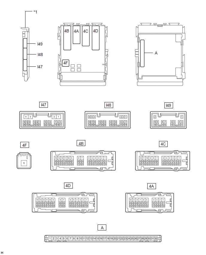
| *1 | Main Body ECU (Multiplex Network Body ECU) | - | - |
(b) Measure the voltage and resistance according to the value(s) in the table below.
HINT:
Measure the values on the wire harness side with the connectors disconnected.
| Tester Connection | Wiring Color | Terminal Description | Condition | Specified Condition |
|---|---|---|---|---|
| A-11 (GND1) - Body ground | - | Ground | Always | Below 1 Ω |
| A-31 (BECU) - Body ground | - | Battery power supply | Power switch off | 11 to 14 V |
| A-30 (ACC) - Body ground | - | ACC power supply | Power switch on (ACC) | 11 to 14 V |
| A-30 (ACC) - Body ground | - | ACC power supply | Power switch off | Below 1 V |
| A-32 (IG) - Body ground | - | IG power supply | Power switch on (IG) | 11 to 14 V |
| A-32 (IG) - Body ground | - | IG power supply | Power switch off | Below 1 V |
(c) Measure the pulse according to the value(s) in the table below.
| Tester Connection | Wiring Color | Terminal Description | Condition | Specified Condition |
|---|---|---|---|---|
| A-16 (LIN2) - Body ground | - | LIN communication line | Power switch on (IG) | Pulse generation |
CHECK MULTIPLEX NETWORK MASTER SWITCH ASSEMBLY
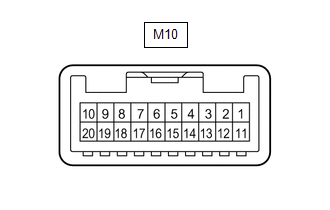
(a) Disconnect the M10 multiplex network master switch assembly connector.
(b) Measure the resistance and voltage according to the value(s) in the table below.
| Terminal No. (Symbol) | Wiring Color | Terminal Description | Condition | Specified Condition |
|---|---|---|---|---|
| M10-11 (B) - Body ground | SB - Body ground | Battery power supply | Power switch off | 11 to 14 V |
| M10-12 (GND) - Body ground | W-B - Body ground | Ground | Always | Below 1 Ω |
(c) Measure the pulse according to the value(s) in the table below.
| Terminal No. (Symbol) | Wiring Color | Terminal Description | Condition | Specified Condition |
|---|---|---|---|---|
| M10-17 (LIN1) - Body ground | R - Body ground | LIN communication line | Power switch on (IG) | Pulse generation |
CHECK FRONT POWER WINDOW REGULATOR MOTOR ASSEMBLY LH
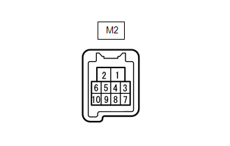
(a) Disconnect the M2 front power window regulator motor assembly LH connector.
(b) Measure the resistance and voltage according to the value(s) in the table below.
| Terminal No. (Symbol) | Wiring Color | Terminal Description | Condition | Specified Condition |
|---|---|---|---|---|
| M2-2 (B) - Body ground | P - Body ground | Battery power supply | Power switch off | 11 to 14 V |
| M2-1 (GND) - Body ground | W-B - Body ground | Ground | Always | Below 1 Ω |
(c) Measure the pulse according to the value(s) in the table below.
| Terminal No. (Symbol) | Wiring Color | Terminal Description | Condition | Specified Condition |
|---|---|---|---|---|
| M2-9 (LIN) - Body ground | W - Body ground | LIN communication line | Power switch on (IG) | Pulse generation |
CHECK FRONT POWER WINDOW REGULATOR MOTOR ASSEMBLY RH
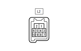
(a) Disconnect the L2 front power window regulator motor assembly RH connector.
(b) Measure the resistance and voltage according to the value(s) in the table below.
| Terminal No. (Symbol) | Wiring Color | Terminal Description | Condition | Specified Condition |
|---|---|---|---|---|
| L2-2 (B) - Body ground | G - Body ground | Battery power supply | Power switch off | 11 to 14 V |
| L2-1 (GND) - Body ground | W-B - Body ground | Ground | Always | Below 1 Ω |
(c) Measure the pulse according to the value(s) in the table below.
| Terminal No. (Symbol) | Wiring Color | Terminal Description | Condition | Specified Condition |
|---|---|---|---|---|
| L2-9 (LIN) - Body ground | SB - Body ground | LIN communication line | Power switch on (IG) | Pulse generation |
CHECK REAR POWER WINDOW REGULATOR MOTOR ASSEMBLY LH
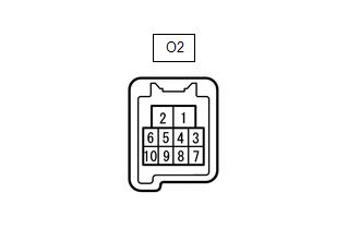
(a) Disconnect the O2 rear power window regulator motor assembly LH connector.
(b) Measure the resistance and voltage according to the value(s) in the table below.
| Terminal No. (Symbol) | Wiring Color | Terminal Description | Condition | Specified Condition |
|---|---|---|---|---|
| O2-2 (B) - Body ground | LA-Y - Body ground | Battery power supply | Power switch off | 11 to 14 V |
| O2-1 (GND) - Body ground | W-B - Body ground | Ground | Always | Below 1 Ω |
(c) Measure the pulse according to the value(s) in the table below.
| Terminal No. (Symbol) | Wiring Color | Terminal Description | Condition | Specified Condition |
|---|---|---|---|---|
| O2-9 (LIN) - Body ground | P - Body ground | LIN communication line | Power switch on (IG) | Pulse generation |
CHECK REAR POWER WINDOW REGULATOR MOTOR ASSEMBLY RH
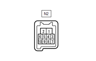
(a) Disconnect the N2 rear power window regulator motor assembly RH connector.
(b) Measure the resistance and voltage according to the value(s) in the table below.
| Terminal No. (Symbol) | Wiring Color | Terminal Description | Condition | Specified Condition |
|---|---|---|---|---|
| N2-2 (B) - Body ground | LA-G - Body ground | Battery power supply | Power switch off | 11 to 14 V |
| N2-1 (GND) - Body ground | W-B - Body ground | Ground | Always | Below 1 Ω |
(c) Measure the pulse according to the value(s) in the table below.
| Terminal No. (Symbol) | Wiring Color | Terminal Description | Condition | Specified Condition |
|---|---|---|---|---|
| N2-9 (LIN) - Body ground | L - Body ground | LIN communication line | Power switch on (IG) | Pulse generation |
CHECK SLIDING ROOF DRIVE GEAR SUB-ASSEMBLY (w/ Sliding Roof System)
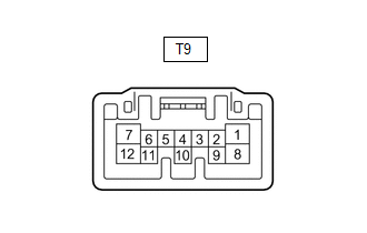
(a) Disconnect the T9 sliding roof drive gear sub-assembly connector.
(b) Measure the resistance and voltage according to the value(s) in the table below.
| Terminal No. (Symbol) | Wiring Color | Terminal Description | Condition | Specified Condition |
|---|---|---|---|---|
| T9-8 (B) - Body ground | W - Body ground | Battery power supply | Power switch off | 11 to 14 V |
| T9-12 (E) - Body ground | W-B - Body ground | Ground | Always | Below 1 Ω |
(c) Measure the pulse according to the value(s) in the table below.
| Terminal No. (Symbol) | Wiring Color | Terminal Description | Condition | Specified Condition |
|---|---|---|---|---|
| T9-11 (MPX1) - Body ground | LG - Body ground | LIN communication line | Power switch on (IG) | Pulse generation |
CHECK CERTIFICATION ECU (SMART KEY ECU ASSEMBLY)
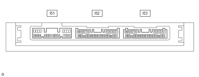
(a) Disconnect the I53 certification ECU connector.
(b) Measure the resistance and voltage according to the value(s) in the table below.
| Terminal No. (Symbol) | Wiring Color | Terminal Description | Condition | Specified Condition |
|---|---|---|---|---|
| I53-10 (+B) - Body ground | W - Body ground | Battery power supply | Power switch off | 11 to 14 V |
| I53-11 (E) - Body ground | W-B - Body ground | Ground | Always | Below 1 Ω |
(c) Measure the pulse according to the value(s) in the table below.
| Terminal No. (Symbol) | Wiring Color | Terminal Description | Condition | Specified Condition |
|---|---|---|---|---|
| I53-6 (LIN) - Body ground | Y - Body ground | LIN communication line | Power switch on (IG) | Pulse generation |
CHECK ID CODE BOX (IMMOBILISER CODE BOX)
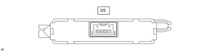
(a) Disconnect the I26 ID code box connector.
(b) Measure the resistance and voltage according to the value(s) in the table below.
| Terminal No. (Symbol) | Wiring Color | Terminal Description | Condition | Specified Condition |
|---|---|---|---|---|
| I26-1 (+B) - Body ground | B - Body ground | Battery power supply | Power switch off | 11 to 14 V |
| I26-5 (GND) - Body ground | W-B - Body ground | Ground | Always | Below 1 Ω |
(c) Measure the pulse according to the value(s) in the table below.
| Terminal No. (Symbol) | Wiring Color | Terminal Description | Condition | Specified Condition |
|---|---|---|---|---|
| I26-2 (LIN1) - Body ground | V - Body ground | LIN communication line | Power switch on (IG) | Pulse generation |
CHECK STEERING LOCK ACTUATOR ASSEMBLY
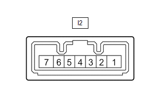
(a) Disconnect the I2 steering lock actuator assembly connector.
(b) Measure the resistance and voltage according to the value(s) in the table below.
| Terminal No. (Symbol) | Wiring Color | Terminal Description | Condition | Specified Condition |
|---|---|---|---|---|
| I2-7 (B) - Body ground | L - Body ground | Battery power supply | Power switch off | 11 to 14 V |
| I2-1 (GND) - Body ground | W-B - Body ground | Ground | Always | Below 1 Ω |
(c) Measure the pulse according to the value(s) in the table below.
| Terminal No. (Symbol) | Wiring Color | Terminal Description | Condition | Specified Condition |
|---|---|---|---|---|
| I2-5 (LIN) - Body ground | G - Body ground | LIN communication line | Power switch on (IG) | Pulse generation |
CHECK AIR CONDITIONING AMPLIFIER ASSEMBLY
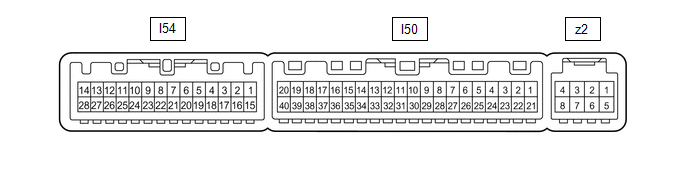
(a) Disconnect the I50 air conditioning amplifier assembly connector.
(b) Measure the resistance and voltage according to the value(s) in the table below.
| Terminal No. (Symbol) | Wiring Color | Terminal Description | Condition | Specified Condition |
|---|---|---|---|---|
| I50-1 (IG+) - Body ground | SB - Body ground | IG power supply | Power switch off | Below 1 V |
| I50-1 (IG+) - Body ground | SB - Body ground | IG power supply | Power switch on (IG) | 11 to 14 V |
| I50-21 (B) - Body ground | GR - Body ground | Battery power supply | Power switch off | 11 to 14 V |
| I50-14 (GND) - Body ground | W-B - Body ground | Ground | Always | Below 1 Ω |
(c) Measure the pulse according to the value(s) in the table below.
| Terminal No. (Symbol) | Wiring Color | Terminal Description | Condition | Specified Condition |
|---|---|---|---|---|
| I50-37 (LIN1) - Body ground | B - Body ground | LIN communication line | Power switch on (IG) | Pulse generation |
CHECK AIR CONDITIONING CONTROL ASSEMBLY

(a) Disconnect the I13 air conditioning control assembly connector.
(b) Measure the resistance and voltage according to the value(s) in the table below.
| Terminal No. (Symbol) | Wiring Color | Terminal Description | Condition | Specified Condition |
|---|---|---|---|---|
| I13-8 (IG+) - Body ground | LG - Body ground | IG power supply | Power switch on (IG) | 11 to 14 V |
| I13-8 (IG+) - Body ground | LG - Body ground | IG power supply | Power switch off | Below 1 V |
| I13-14 (GND) - Body ground | W-B - Body ground | Ground | Always | Below 1 Ω |
(c) Measure the pulse according to the value(s) in the table below.
| Terminal No. (Symbol) | Wiring Color | Terminal Description | Condition | Specified Condition |
|---|---|---|---|---|
| I13-6 (LIN1) - Body ground | B - Body ground | LIN communication line | Power switch on (IG) | Pulse generation |
CHECK RAIN SENSOR (w/ Rain Sensor)
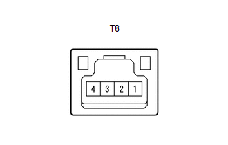
(a) Disconnect the T8 rain sensor connector.
(b) Measure the resistance and voltage according to the value(s) in the table below.
| Terminal No. (Symbol) | Wiring Color | Terminal Description | Condition | Specified Condition |
|---|---|---|---|---|
| T8-4 (SIG) - Body ground | GR - Body ground | IG power supply | Power switch on (IG) | 11 to 14 V |
| T8-4 (SIG) - Body ground | GR - Body ground | IG power supply | Power switch off | Below 1 V |
| T8-2 (ES) - Body ground | W - Body ground | Ground | Always | Below 1 Ω |
(c) Measure the pulse according to the value(s) in the table below.
| Terminal No. (Symbol) | Wiring Color | Terminal Description | Condition | Specified Condition |
|---|---|---|---|---|
| T8-1 (MPX) - Body ground | V - Body ground | LIN communication line | Power switch on (IG) | Pulse generation |
CHECK WINDSHIELD WIPER RELAY ASSEMBLY (w/ Rain Sensor)
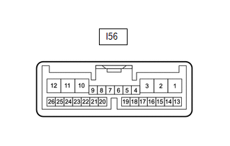
(a) Disconnect the I56 windshield wiper relay assembly connector.
(b) Measure the resistance and voltage according to the value(s) in the table below.
| Terminal No. (Symbol) | Wiring Color | Terminal Description | Condition | Specified Condition |
|---|---|---|---|---|
| I56-2 (IG) - Body ground | L - Body ground | IG power supply | Power switch on (IG) | 11 to 14 V |
| I56-2 (IG) - Body ground | L - Body ground | IG power supply | Power switch off | Below 1 V |
| I56-12 (E) - Body ground | W-B - Body ground | Ground | Always | Below 1 Ω |
| I56-16 (WIG) - Body ground | L - Body ground | Battery power supply | Power switch on (IG) | 11 to 14 V |
| Power switch off | Below 1 V |
(c) Measure the pulse according to the value(s) in the table below.
| Terminal No. (Symbol) | Wiring Color | Terminal Description | Condition | Specified Condition |
|---|---|---|---|---|
| I56-14 (MPX1) - Body ground | V - Body ground | LIN communication line | Power switch on (IG) | Pulse generation |
CHECK KICK DOOR CONTROL SENSOR (w/ Hands Free Power Back Door)
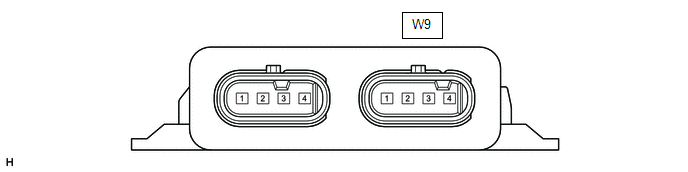
(a) Disconnect the W9 kick door control sensor connector.
(b) Measure the resistance and voltage according to the value(s) in the table below.
| Terminal No. (Symbol) | Wiring Color | Terminal Description | Condition | Specified Condition |
|---|---|---|---|---|
| W9-1 (B) - Body ground | Y - Body ground | Battery power supply | Always | 11 to 14 V |
| W9-4 (GND) - Body ground | W-B - Body ground | Ground | Always | Below 1 Ω |
(c) Measure the pulse according to the value(s) in the table below.
| Terminal No. (Symbol) | Wiring Color | Terminal Description | Condition | Specified Condition |
|---|---|---|---|---|
| W9-2 (LIN) - Body ground | P - Body ground | LIN communication line | Engine switch on (IG) | Pulse generation |
READ NEXT:
 Dtc Check / Clear
DTC CHECK / CLEAR CHECK DTC (a) Check main body ECU (multiplex network body ECU) (1) Connect the Techstream to the DLC3. (2) Turn the power switch on (IG). (3) Turn the Techstream on. (4) Enter the fo
Data List / Active Test
DATA LIST / ACTIVE TEST READ DATA LIST NOTICE: In the table below, the values listed under "Normal Condition" are reference values. Do not depend solely on these reference values when deciding whether
Diagnostic Trouble Code Chart
DIAGNOSTIC TROUBLE CODE CHART LIN Communication System DTC No. Detection Item Link B1206 P/W Master Switch Communication Stop B1273 Sliding Roof ECU Communication Stop
SEE MORE:
Rear Door LH ECU Communication Stop (B2324)
DESCRIPTION This DTC is output when LIN communication between the rear power window regulator motor assembly LH and main body ECU (multiplex network body ECU) stops for 10 seconds or more. DTC No. Detection Item DTC Detection Condition Trouble Area B2324 Rear Door LH ECU Communication
Accessory Socket System
Parts LocationPARTS LOCATION ILLUSTRATION *1 VOLTAGE INVERTER ASSEMBLY *2 NO. 2 POWER OUTLET SOCKET ASSEMBLY *3 INSTRUMENT PANEL JUNCTION BLOCK ASSEMBLY - ECU-IG NO.1 FUSE *4 NO. 2 ENGINE ROOM RELAY BLOCK - INV FUSE *5 NO. 3 RELAY BLOCK - INV RELAY - System Di
