Lexus NX: Terminals Of Ecu
TERMINALS OF ECU
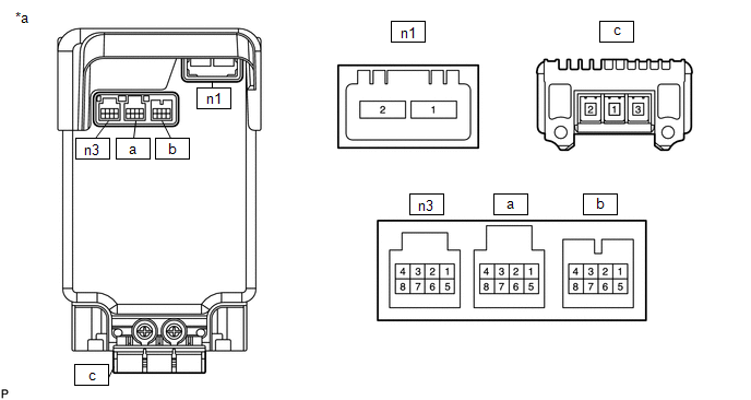
| *a | Component with harness connected (Power Steering ECU Assembly) | - | - |
CHECK POWER STEERING ECU ASSEMBLY
(a) Measure the voltage and resistance according to the value(s) in the table below.
NOTICE:
When the power steering warning light (red) is illuminated due to a malfunction, the fail-safe function may cause the voltage of the power steering ECU assembly terminals to become 0 V.
| Terminal No. (Symbol) | Wiring Color | Terminal Description | Condition | Specified Condition |
|---|---|---|---|---|
| n3-1 (IG) - n1-2 (PGND) | R - B | IG power source | Power switch on (IG) | 8 to 16 V |
| n3-4 (CANH) - n3-8 (CANL) | W - B | CAN communication line | Power switch off | 54 to 69 Ω |
| n3-5 (TS) - n1-2 (PGND) | O - B | Terminal TS of DLC3 | Always | 9 to 16 V |
| a-1 (TRQG) - Body ground | - (Not available) - Body ground | Torque sensor ground | Always | Below 1 Ω |
| a-2 (TRQ2) - a-1 (TRQG) | - (Not available) | Torque sensor signal | Power switch on (READY) Steering wheel not being turned (without load) | 2.3 to 2.7 V |
| Power switch on (READY) Steering wheel being turned to right with vehicle stopped | 0.3 to 2.5 V | |||
| Power switch on (READY) Steering wheel being turned to left with vehicle stopped | 2.5 to 4.7 V | |||
| a-3 (TRQV) - a-1 (TRQG) | - (Not available) | Torque sensor voltage source | Power switch on (READY) | 8.5 to 10.5 V |
| a-5 (TRQF) - a-1 (TRQG) | - (Not available) | Torque sensor reference voltage | Power switch on (READY) | 3.35 to 3.37 V |
| a-7 (TRQ1) - a-1 (TRQG) | - (Not available) | Torque sensor signal | Power switch on (READY) Steering wheel not being turned (without load) | 2.3 to 2.7 V |
| Power switch on (READY) Steering wheel being turned to right with vehicle stopped | 2.5 to 4.7 V | |||
| Power switch on (READY) Steering wheel being turned to left with vehicle stopped | 0.3 to 2.5 V | |||
| b-1 (RZCS2) - n1-2 (PGND) | B - B | Rotation angle sensor COS aspect output signal | Power switch on (READY) Steering wheel turned | 0.68 to 4.42 V |
| b-2 (RZV2) - n1-2 (PGND) | G - B | Rotation angle sensor excitation output signal | Power switch on (READY) Steering wheel turned | 0.68 to 4.42 V |
| b-3 (RZSN2) - n1-2 (PGND) | L - B | Rotation angle sensor SIN aspect output signal | Power switch on (READY) Steering wheel turned | 0.68 to 4.42 V |
| b-5 (RZCS1) - n1-2 (PGND) | R - B | Rotation angle sensor COS aspect output signal | Power switch on (READY) Steering wheel turned | 0.68 to 4.42 V |
| b-6 (RZV1) - n1-2 (PGND) | W - B | Rotation angle sensor excitation output signal | Power switch on (READY) Steering wheel turned | 0.68 to 4.42 V |
| b-7 (RZSN1) - n1-2 (PGND) | Y - B | Rotation angle sensor SIN aspect output signal | Power switch on (READY) Steering wheel turned | 0.68 to 4.42 V |
| n1-1 (PIG) - n1-2 (PGND) | R - B | Power source | Always | 9 to 16 V |
| n1-2 (PGND) - Body ground | B - Body ground | Power ground | Always | Below 1 Ω |
| c-1 (PHA) - n1-2 (PGND) | # - B | A phase motor output | Power switch on (READY) Steering wheel turned | Value changes within 4 to 35 V range |
| c-2 (PHB) - n1-2 (PGND) | # - B | B phase motor output | Power switch on (READY) Steering wheel turned | Value changes within 4 to 35 V range |
| c-3 (PHC) - n1-2 (PGND) | # - B | C phase motor output | Power switch on (READY) Steering wheel turned | Value changes within 4 to 35 V range |
HINT:
# means that the motor terminal is tightened directly to the ECU with bolts.
READ NEXT:
 Diagnosis System
DIAGNOSIS SYSTEM CHECK DLC3 (a) Check the DLC3. Click here CHECK WARNING LIGHT (a) When a problem occurs in the power steering system, the power steering warning light (red or yellow) on the combina
Dtc Check / Clear
DTC CHECK / CLEAR CHECK DTC (USING THE Techstream) (a) Turn the power switch off. (b) Connect the Techstream to the DLC3. (c) Turn the power switch on (IG). (d) Turn the Techstream on. (e) Enter the f
Freeze Frame Data
FREEZE FRAME DATA FREEZE FRAME DATA NOTICE:
It is difficult to show the specified values (judgment values) clearly because freeze frame data values change significantly due to differences in measur
SEE MORE:
Speaker Circuit
DESCRIPTION If there is a short in a speaker circuit, the stereo component amplifier assembly detects it and stops output to the speakers. As a result, sound cannot be heard from the speakers even if there is no malfunction in the stereo component amplifier assembly, DCM (telematics transceiver)* or
Components
COMPONENTS ILLUSTRATION *1 DECK FLOOR BOX LH *2 NO. 3 DECK BOARD SUB-ASSEMBLY *3 REAR DECK FLOOR BOX *4 AUXILIARY BATTERY NEGATIVE TERMINAL N*m (kgf*cm, ft.*lbf): Specified torque - - ILLUSTRATION *1 FRONT AIRBAG SENSOR LH - - N*m (kgf*cm, ft.*lbf):
