Lexus NX: Terminals Of Ecu
TERMINALS OF ECU
CHECK VEHICLE APPROACHING SPEAKER CONTROLLER

(a) Disconnect the A80 vehicle approaching speaker controller connector.
(b) Measure the voltage and resistance according to the value(s) in the table below.
| Terminal No. (Symbol) | Wiring Color | Terminal Description | Condition | Specified Condition |
|---|---|---|---|---|
| A80-1 (IG) - Body ground | L - Body ground | IG power supply | Power switch on (IG) | 11 to 14 V |
| Power switch off | Below 1 V | |||
| A80-6 (GND) - Body ground | W-B - Body ground | Ground | Always | Below 1 Ω |
(c) Connect the A80 vehicle approaching speaker controller connector.
(d) Measure the check for pulses according to the value(s) in the table below.
| Terminal No. (Symbol) | Wiring Color | Terminal Description | Condition | Specified Condition |
|---|---|---|---|---|
| A80-7 (SP+) - A80-8 (SP-) | L - B | Vehicle approaching speaker output | Vehicle approaching speaker operating | A waveform synchronized with the sound is output. (See Waveform 1) |
| A80-3 (CANH) - A80-6 (GND) | V - W-B | CAN communication line | Power switch on (IG) | Pulse generation |
| A80-4 (CANL) - A80-6 (GND) | W - W-B | CAN communication line | Power switch on (IG) | Pulse generation |
(1) Waveform 1
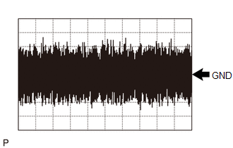
| Item | Condition |
|---|---|
| Tester Connection | A80-7 (SP+) - A80-8 (SP-) |
| Tool Setting | 1 V/DIV., 500 ms./DIV. |
| Condition | Vehicle approaching speaker operating |
READ NEXT:
 Dtc Check / Clear
DTC CHECK / CLEAR DTC CHECK (a) Connect the Techstream to the DLC3. (b) Turn the power switch on (IG). (c) Turn the Techstream on. (d) Enter the following menus: Body Electrical / Vehicle Proximity No
Data List / Active Test
DATA LIST / ACTIVE TEST DATA LIST NOTICE: In the table below, the values listed under "Normal Condition" are reference values. Do not depend solely on these reference values when deciding whether a pa
Diagnostic Trouble Code Chart
DIAGNOSTIC TROUBLE CODE CHART Vehicle Proximity Notification System DTC No. Detection Item Link B1350 Speaker Circuit U0129 Lost Communication with Brake System Control Module
SEE MORE:
Internal Control Module EEPROM Error (P062F)
DESCRIPTION The ECM monitors its internal operation and stores this DTC when it detects an internal malfunction. DTC No. Detection Item DTC Detection Condition Trouble Area MIL Memory P062F Internal Control Module EEPROM Error An ECM internal error (EEPROM) (1 trip detection log
Noise Occurs
PROCEDURE 1. CHECK NOISE CONDITION (a) Check from which direction the noise comes (front left or right, or rear left or right). OK: The location of the noise source can be determined. NG GO TO STEP 3
OK 2. CHECK SPEAKERS (a) Check the installation condi
