Lexus NX: Terminals Of Ecu
TERMINALS OF ECU
CHECK INSTRUMENT PANEL JUNCTION BLOCK ASSEMBLY, MAIN BODY ECU (MULTIPLEX NETWORK BODY ECU)
(a) Remove the main body ECU (multiplex network body ECU) from the instrument panel junction block assembly.
Click here .gif)
.png)
| *1 | Main Body ECU (Multiplex Network Body ECU) | - | - |
(b) Connect the instrument panel junction block assembly connectors.
(c) Measure the voltage and resistance according to the value(s) in the table below.
| Terminal No. (Symbol) | Wiring Color | Terminal Description | Condition | Specified Condition |
|---|---|---|---|---|
| A-32 (IG) - Body ground | - | Ignition power supply | Power switch off | Below 1 V |
| Power switch on (IG) | 11 to 14 V | |||
| A-31 (BECU) - Body ground | - | Battery power supply | Power switch off | 11 to 14 V |
| A-30 (ACC) - Body ground | - | ACC power supply | Power switch off | Below 1 V |
| Power switch on (ACC) | 11 to 14 V | |||
| A-11 (GND1) - Body ground | - | Ground | Always | Below 1 Ω |
(d) Install the main body ECU (multiplex network body ECU).
Click here
(e) Measure the voltage and pulse according to the value(s) in the table below.
| Terminal No. (Symbol) | Wiring Color | Terminal Description | Condition | Specified Condition |
|---|---|---|---|---|
| I48-1 (DIM) - Body ground | L - Body ground | H-LP RH relay drive output | Power switch off | 11 to 14 V |
| Power switch on (IG) | Below 1 V | |||
| I48-8 (A) - Body ground | G - Body ground | Headlight dimmer switch AUTO signal input | Headlight dimmer switch not in AUTO position | 11 to 14 V |
| Headlight dimmer switch in AUTO position | Below 1 V | |||
| I48-10 (HF) - Body ground | R - Body ground | Headlight dimmer switch high flash signal input | Headlight dimmer switch not in high flash position | 11 to 14 V |
| Headlight dimmer switch in high flash position | Below 1 V | |||
| I48-12 (HEAD) - Body ground | LG - Body ground | Headlight dimmer switch head signal input | Headlight dimmer switch not in head position | 11 to 14 V |
| Headlight dimmer switch in head position | Below 1 V | |||
| I48-19 (CLTB) - I48-21 (CLTE) | W - V | Automatic light control sensor power supply output | Power switch on (IG) | 11 to 14 V |
| I48-22 (TAIL) - Body ground | P - Body ground | Headlight dimmer switch tail signal input | Headlight dimmer switch in neither tail nor head position | 11 to 14 V |
| Headlight dimmer switch in tail or head position | Below 1 V | |||
| I48-24 (HU) - Body ground | Y - Body ground | Headlight dimmer switch high signal input | Headlight dimmer switch in low position | 11 to 14 V |
| Headlight dimmer switch in high position | Below 1 V | |||
| I48-26 (FFOG) - Body ground | GR - Body ground | Front fog light switch input | Front fog light switch off | 11 to 14 V |
| Front fog light switch on | Below 1 V | |||
| 4B-53 (HRLY) - Body ground | L - Body ground | H-LP LH DIMMER (HI) relay drive output | Power switch off | 11 to 14 V |
| Power switch on (IG) | Below 1 V | |||
| 4B-56 (FFGO) - Body ground | W - Body ground | Front fog light signal output | Headlight dimmer switch in tail or head position and front fog light switch off | 11 to 14 V |
| Headlight dimmer switch in tail or head position and front fog light switch on | Below 1 V | |||
| I48-20 (CLTS) - Body ground | P - Body ground | Automatic light control sensor signal input | Power switch on (IG), headlight dimmer switch in AUTO position and automatic light control sensor covered with a hand → Automatic light control sensor exposed to ambient light | Pulse generation (waveform varies depending on light volume) |
| I48-6 (FLCY) - Body ground | G - Body ground | Front door courtesy light switch LH signal | Front door LH open | Below 1 V |
| Front door LH closed | Pulse generation |
CHECK COMBINATION METER ASSEMBLY
.png)
(a) Disconnect the I10 and I11 combination meter connectors.
(b) Measure the resistance and voltage according to the value(s) in the table below.
| Terminal No. (Symbol) | Wiring Color | Terminal Description | Condition | Specified Condition |
|---|---|---|---|---|
| I10-22 (B) - Body ground | Y - Body ground | Battery power supply | Power switch off | 11 to 14 V |
| I10-21 (IG+) - Body ground | B - Body ground | Ignition power supply | Power switch off | Below 1 V |
| Power switch on (IG) | 9.5 to 14 V | |||
| I11-1 (B) - Body ground | L - Body ground | Battery power supply | Power switch off | 11 to 14 V |
| I11-2 (HZSW) - Body ground | B - Body ground | Hazard warning signal switch signal input | Hazard warning signal switch off | 11 to 14 V |
| Hazard warning signal switch on | Below 1 V | |||
| I11-12 (HAZM) - Body ground | R - Body ground | Hazard warning signal switch signal input | Hazard warning signal switch off | Below 1 V → 11 to 14 V |
| Hazard warning signal switch on | Below 1 V | |||
| I10-32 (ES) - Body ground | W-B - Body ground | Ground | Always | Below 1 Ω |
(c) Reconnect the I10 and I11 combination meter connectors.
(d) Measure the voltage according to the value(s) in the table below.
| Terminal No. (Symbol) | Wiring Color | Terminal Description | Condition | Specified Condition |
|---|---|---|---|---|
| I11-3 (ER) - Body ground | L - Body ground | Turn signal switch (right turn position) signal input | Power switch on (IG) Turn signal switch off | 11 to 14 V |
| Power switch on (IG) Turn signal switch in right turn position | Below 1 V | |||
| I11-4 (EL) - Body ground | R - Body ground | Turn signal switch (left turn position) signal input | Power switch on (IG) Turn signal switch off | 11 to 14 V |
| Power switch on (IG) Turn signal switch in left turn position | Below 1 V | |||
| I11-8 (SW) - Body ground | B - Body ground | Turn signal switch (full turn position) signal input | Power switch on (IG) Turn signal switch off | 11 to 14 V |
| Power switch on (IG) Turn signal switch in full turn position | Below 1 V | |||
| I11-7 (LR) - Body ground | L - Body ground | RH turn signal light signal output | Power switch on (IG) RH turn signal light off | Below 1 V |
| Power switch on (IG) RH turn signal light blinking | Below 1 V ←→ 11 to 14 V | |||
| I11-13 (LL) - Body ground | Y - Body ground | LH turn signal light signal output | Power switch on (IG) LH turn signal light off | Below 1 V |
| Power switch on (IG) LH turn signal light blinking | Below 1 V ←→ 11 to 14 V | |||
| I11-5 (TRNR) - Body ground | SB - Body ground | RH turn signal light signal output | Power switch on (IG) RH turn signal light off | Below 1 V |
| Power switch on (IG) RH turn signal light blinking | Below 1 V ←→ 11 to 14 V | |||
| I11-11 (TRNL) - Body ground | Y - Body ground | LH turn signal light signal output | Power switch on (IG) LH turn signal light off | Below 1 V |
| Power switch on (IG) LH turn signal light blinking | Below 1 V ←→ 11 to 14 V |
CHECK HEADLIGHT ECU SUB-ASSEMBLY LH
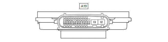
(a) Disconnect the A19 headlight ECU sub-assembly LH connector.
(b) Measure the resistance and voltage according to the value(s) in the table below.
| Terminal No. (Symbol) | Wiring Color | Terminal Description | Condition | Specified Condition |
|---|---|---|---|---|
| A19-4 (IG) - Body ground | L - Body ground | Ignition power supply | Power switch off | Below 1 V |
| Power switch on (IG) | 11 to 14 V | |||
| A19-13 (ECUB) - Body ground | R - Body ground | Power supply | Headlight off | Below 1 V |
| Headlight on | 11 to 14 V | |||
| A19-12 (GND) - Body ground | W-B - Body ground | Ground | Always | Below 1 Ω |
(c) Reconnect the A19 headlight ECU sub-assembly LH connector.
HINT:
Since the headlight ECU sub-assembly LH uses waterproof connectors, the voltage, resistance and waveform cannot be checked directly. The voltage, resistance and waveform are indicated for reference only.
(d) Measure the voltage and pulse according to the value(s) in the table below.
| Terminal No. (Symbol) | Wiring Color | Terminal Description | Condition | Specified Condition |
|---|---|---|---|---|
| A19-8 (RLD2) - Body ground | L - Body ground | Daytime running light system drive output | Daytime running light on | No pulse |
| Daytime running light off | Pulse generation | |||
| A19-11 (TNS) - Body ground | W - Body ground | LH turn signal light signal output | LH turn signal light blinking | Below 1 V ←→ 11 to 14 V |
| LH turn signal light off | Below 1 V | |||
| A19-16 (SBR) - A19-15 (SGR) | R - P | Rear height control sensor power supply | Power switch on (IG) | Approximately 5 V |
| A19-17 (SHRL) - A19-15 (SGR) | L - P | Rear height control sensor signal input | (No passengers, no luggage, vehicle not moving) | Approximately 2.5 V (vehicle level) (value decreases as the front of the vehicle is raised) |
| A19-20 (LINL) - Body ground | LG - Body ground | LIN communication | Power switch on (IG) | Below 1 V |
CHECK HEADLIGHT ECU SUB-ASSEMBLY RH
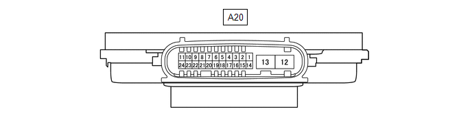
(a) Disconnect the A20 headlight ECU sub-assembly RH connector.
(b) Measure the resistance and voltage according to the value(s) in the table below.
| Terminal No. (Symbol) | Wiring Color | Terminal Description | Condition | Specified Condition |
|---|---|---|---|---|
| A20-4 (IG) - Body ground | G - Body ground | Ignition power supply | Power switch off | Below 1 V |
| Power switch on (IG) | 11 to 14 V | |||
| A20-13 (ECUB) - Body ground | B - Body ground | Power supply | Headlight off | Below 1 V |
| Headlight on | 11 to 14 V | |||
| A20-12 (GND) - Body ground | W-B - Body ground | Ground | Always | Below 1 Ω |
(c) Reconnect the A20 headlight ECU sub-assembly RH connector.
HINT:
Since the headlight ECU sub-assembly RH uses waterproof connectors, the voltage, resistance and waveform cannot be checked directly. The voltage, resistance and waveform are indicated for reference only.
(d) Measure the voltage and pulse according to the value(s) in the table below.
| Terminal No. (Symbol) | Wiring Color | Terminal Description | Condition | Specified Condition |
|---|---|---|---|---|
| A20-8 (RLD2) - Body ground | L - Body ground | Daytime running light system drive output | Daytime running light on | No pulse |
| Daytime running light off | Pulse generation | |||
| A20-11 (TNS) - Body ground | L - Body ground | RH turn signal light signal output | RH turn signal light blinking | Below 1 V ←→ 11 to 14 V |
| RH turn signal light off | Below 1 V | |||
| A20-20 (LINL) - Body ground | LG - Body ground | LIN communication | Power switch on (IG) | Below 1 V |
READ NEXT:
 Diagnosis System
DIAGNOSIS SYSTEM DESCRIPTION (a) Lighting system data and the Diagnostic Trouble Codes (DTCs) can be read from the Data Link Connector 3 (DLC3) of the vehicle. When the system seems to be malfunctioni
Dtc Check / Clear
DTC CHECK / CLEAR CHECK FOR DTC (a) Connect the Techstream to the DLC3. (b) Turn the power switch on (IG). (c) Turn the Techstream on. (d) Enter the following menus: Body Electrical / Main body / Trou
Freeze Frame Data
FREEZE FRAME DATA FREEZE FRAME DATA (a) Whenever a DTC is detected, the headlight ECU sub-assembly or front recognition camera stores the current vehicle (sensor) state as freeze frame data. CHECK FRE
SEE MORE:
Cruise Main Indicator Light Circuit
DESCRIPTION When the dynamic radar cruise control system is turned on using the cruise control main switch, the cruise control indicator (vehicle-to-vehicle distance control mode) illuminates. The hybrid vehicle control ECU uses this and other indicators to indicate the status (presence or absence o
Replacement
REPLACEMENT PROCEDURE 1. RECOVER REFRIGERANT FROM REFRIGERATION SYSTEM (a) Turn the power switch on (READY). (b) Operate the cooler compressor under the conditions shown below: Item Condition Operating time 3 minutes or more Temperature setting Max cool Blower speed High E
