Lexus NX: Replacement
REPLACEMENT
PROCEDURE
1. RECOVER REFRIGERANT FROM REFRIGERATION SYSTEM
(a) Turn the power switch on (READY).
(b) Operate the cooler compressor under the conditions shown below:
| Item | Condition |
|---|---|
| Operating time | 3 minutes or more |
| Temperature setting | Max cool |
| Blower speed | High |
| Engine | On (READY) |
| A/C switch | On |
This causes most of the compressor oil from the various components of the A/C system to collect in the A/C compressor.
HINT:
It is not necessary to operate the cooler compressor if the A/C does not operate because of compressor lock etc.
(c) Turn the power switch off.
(d) Recover the refrigerant from the A/C system using a refrigerant recovery unit.
HINT:
Use the refrigerant recovery unit in accordance with the manufacturer's instruction manual.
2. CHARGE AIR CONDITIONING SYSTEM WITH REFRIGERANT
HINT:
Charge refrigerant in accordance with the equipment manual.
(a) Perform vacuum purging using a vacuum pump or appropriate equipment.
NOTICE:
Be sure to use a refrigerant recovery unit that is compatible with HFO-1234yf (R1234yf) systems.
(b) Charge the air conditioning system with refrigerant.
Refrigerant Type:
HFO-1234yf (R1234yf)
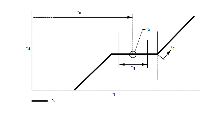
| *a | Standard Charge Amount | *b | Mean Value in Proper Range |
| *c | Overcharged | *d | High Pressure |
| *e | Sub-cool System | *f | Refrigerant Amount |
| *g | +/-30 g (+/-1.06 oz) | - | - |
Standard charge amount:
470 to 530 g (16.6 to 18.7 oz)
NOTICE:
- Make sure that the amount of refrigerant is within 30 g (1.06 oz.) of the specified amount.
- Do not turn the A/C switch on before charging the air conditioning system with refrigerant. Doing so may cause the compressor to work without refrigerant, resulting in overheating of the compressor.
- The refrigerant amount should be checked by quantity (weight).
HINT:
Ensure that sufficient refrigerant is available to recharge the system when using a refrigerant recovery unit. Refrigerant recovery units are not always able to recover 100% of the refrigerant from an air conditioning system.
3. WARM UP COMPRESSOR
(a) Keep the A/C switch on for at least 2 minutes to warm up the compressor.
NOTICE:
To prevent damage to the compressor, be sure to warm up the compressor when turning the air conditioning on after removing and installing air conditioning system lines (including the compressor).
4. INSPECT FOR REFRIGERANT LEAK
(a) After recharging the air conditioning system with refrigerant, inspect for refrigerant leaks using a gas leak detector.
HINT:
Be sure to use a gas leak detector that is compatible with HFO-1234yf (R1234yf) systems.
(b) Carry out the test under the following conditions:
- Turn the power switch off.
- Ensure good ventilation (the gas leak detector may react to volatile gases which are not refrigerant, such as gasoline vapor and exhaust gas).
- Repeat the inspection 2 or 3 times.
-
Measure the pressure to make sure that there is some refrigerant remaining in the air conditioning system.
Pressure when the compressor is off: approximately 392 to 588 kPa (3.9 to 5.9 kgf/cm2, 57 to 85 psi).
| (c) Using a gas leak detector, inspect for refrigerant leaks from the air conditioning system. |
|
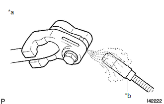
| (d) Bring the gas leak detector close to the drain hose with the detector power off, and then turn the detector on. HINT:
|
|
(e) If a refrigerant leak is not detected from the drain hose, remove the blower motor control from the cooling unit. Insert the gas leak detector sensor into the unit and check for a leak.
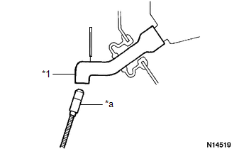
(f) Disconnect the pressure sensor connector and leave it for approximately 20 minutes. Bring the gas leak detector close to the pressure sensor and check for a leak.
HINT:
When checking for leaks, the presence of oily dirt at a joint can indicate a leak.
READ NEXT:
 Refrigerant Line
ComponentsCOMPONENTS ILLUSTRATION *1 LIQUID TUBE SUB-ASSEMBLY *2 DISCHARGE HOSE SUB-ASSEMBLY *3 SUCTION HOSE SUB-ASSEMBLY *4 AIR CONDITIONER TUBE AND ACCESSORY ASSEMBLY *5 P
Relay
On-vehicle InspectionON-VEHICLE INSPECTION PROCEDURE 1. INSPECT PTC HEATER RELAY(PTC HTR NO. 1, NO. 3) (a) Measure the resistance according to the value(s) in the table below. Standard Resistance:
SEE MORE:
Diagnosis System
DIAGNOSIS SYSTEM CHECK DLC3 (a) Check the DLC3. Click here FUNCTION OF PASSENGER AIRBAG ON/OFF INDICATOR (a) Initial check (1) Turn the power switch on (IG). (2) The passenger airbag ON/OFF indicator comes on for approximately 4 seconds, and then goes off for approximately 2 seconds. (3) Approxim
CAN Communication Failure (Message Registry) (U1000)
DESCRIPTION This DTC is stored when the rear television camera assembly judges that it has an internal CAN malfunction. DTC No. Detection Item DTC Detection Condition Trouble Area U1000 CAN Communication Failure (Message Registry) Can communication failure (message registry) Rear
