Lexus NX: Terminals Of Ecu
TERMINALS OF ECU
CHECK MAIN BODY ECU (MULTIPLEX NETWORK BODY ECU), INSTRUMENT PANEL JUNCTION BLOCK ASSEMBLY
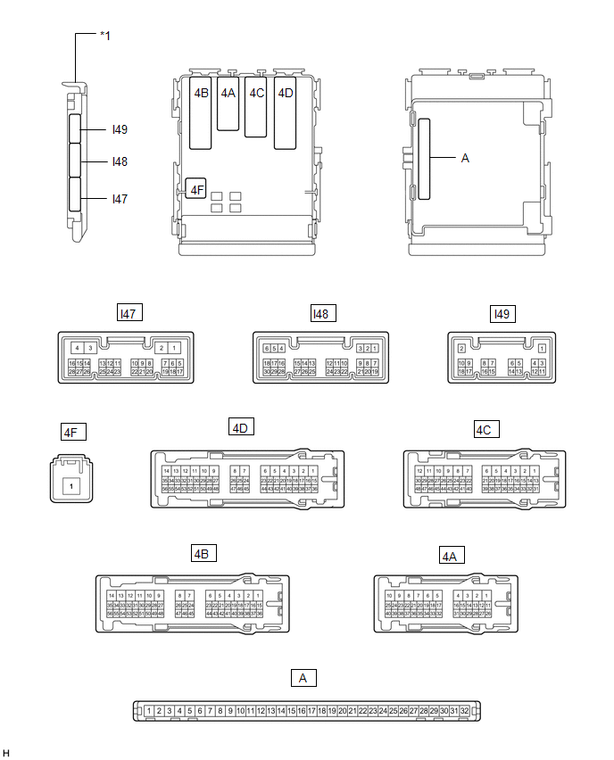
| *1 | Main Body ECU (Multiplex Network Body ECU) | - | - |
(a) Remove the main body ECU (multiplex network body ECU) from the instrument panel junction block assembly.
Click here .gif)
(b) Measure the voltage and resistance according to the value(s) in the table below.
| Tester Connection | Wiring Color | Terminal Description | Condition | Specified Condition |
|---|---|---|---|---|
| 4F-1 - Body ground | B - Body ground | Power source | Power switch off | 11 to 14 V |
| A-32 (IG) - Body ground | None - Body ground | Power source (IG) | Power switch off → on (IG) | Below 1 V → 11 to 14 V |
| A-30 (ACC) - Body ground | None - Body ground | Power source (ACC) | Power switch off → on (ACC) | Below 1 V → 11 to 14 V |
| A-31 (BECU) - Body ground | None - Body ground | Power source | Power switch off | 11 to 14 V |
| A-11 (GND1) - Body ground | None - Body ground | Ground | Always | Below 1 Ω |
(c) Install the main body ECU (multiplex network body ECU) to the instrument panel junction block assembly.
Click here
(d) Measure the voltage according to the value(s) in the table below.
| Tester Connection | Wiring Color | Terminal Description | Condition | Specified Condition |
|---|---|---|---|---|
| I47-14 (RET) - Body ground | G - Body ground | Outer mirror switch assembly signal | Outer mirror switch assembly (mirror retract switch) return position → retract position | Below 1 V → 11 to 14 V |
| I47-15 (RTR) - Body ground | LG - Body ground | Outer mirror switch assembly signal | Outer mirror switch assembly (mirror retract switch) retract position → return position | Below 1 V → 11 to 14 V |
| I47-19 (RETR) - Body ground | L - Body ground | E-MIR2 relay drive signal | Retract function is operating → retract function is not operating | Below 1 V → 11 to 14 V |
| I47-20 (RTRR) - Body ground | GR - Body ground | E-MIR1 relay drive signal | Return function is operating → return function is not operating | Below 1 V → 11 to 14 V |
CHECK AIR CONDITIONING AMPLIFIER ASSEMBLY
Click here
CHECK AIR CONDITIONING CONTROL ASSEMBLY
Click here
READ NEXT:
 Diagnosis System
DIAGNOSIS SYSTEM CHECK DLC3 (a) Check the DLC3. Click here INSPECT AUXILIARY BATTERY VOLTAGE (a) Measure the auxiliary battery voltage with the power switch off. Standard voltage: 11 to 14 V If th
Data List / Active Test
DATA LIST / ACTIVE TEST DATA LIST HINT: Using the Techstream to read the Data List allows the values or states of switches, sensors, actuators and other items to be read without removing any parts. Th
Mirror Heater does not Operate with Rear Defogger Switch
DESCRIPTION When the rear window defogger switch (mirror heater switch) on the air conditioning control assembly is pressed, the operation signal is transmitted to the air conditioning amplifier assem
SEE MORE:
Precaution
PRECAUTION PRECAUTIONS FOR HANDS FREE POWER BACK DOOR (w/ Hands Free Power Back Door) (a) In the following situations, the hands free power back door may operate unintentionally if the electrical transmitter key sub-assembly is near or within the rear door exterior detection area: HINT: Refer to sma
MIL Circuit
DESCRIPTION The Malfunction Indicator Lamp (MIL) is used to indicate vehicle malfunctions detected by the ECM. The MIL operation can be checked visually. When the power switch is turned on (IG), the MIL should be illuminated and should then turn off after the power switch on (READY). If the MIL rema
