Lexus NX: MIL Circuit
DESCRIPTION
The Malfunction Indicator Lamp (MIL) is used to indicate vehicle malfunctions detected by the ECM.
The MIL operation can be checked visually. When the power switch is turned on (IG), the MIL should be illuminated and should then turn off after the power switch on (READY). If the MIL remains illuminated or is not illuminated, conduct the following troubleshooting procedure using the Techstream.
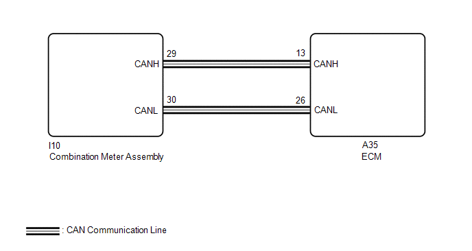
WIRING DIAGRAM
PROCEDURE
| 1. | CHECK THAT MIL IS ILLUMINATED |
(a) Perform troubleshooting in accordance with the table below.
| MIL | Condition | Proceed to |
|---|---|---|
| Illuminates → Turns off | Power switch on (IG) → engine is started | A |
| Other than above | - | B |
| A | .gif) | CHECK FOR INTERMITTENT PROBLEMS |
|
.gif)
| 2. | CHECK COMMUNICATION BETWEEN TECHSTREAM AND ECM |
(a) Connect the Techstream to the DLC3.
(b) Turn the power switch on (IG).
(c) Turn the Techstream on.
(d) Check the communication between the Techstream and ECM.
HINT:
It can be checked using the "Engine" item of the Data List.
| Result | Proceed to |
|---|---|
| Communication is possible | A |
| Communication is not possible | B |
| B | | GO TO VC OUTPUT CIRCUIT |
|
| 3. | CHECK WHETHER DTC OUTPUT RECURS |
(a) Connect the Techstream to the DLC3.
(b) Turn the power switch on (IG).
(c) Turn the Techstream on.
(d) Enter the following menus: System Select / Health Check.
(e) Check if any DTCs have been detected. Note down any DTCs.
| Result | Proceed to |
|---|---|
| DTCs are not output | A |
| DTCs are output | B |
HINT:
Check for detected DTCs output from other ECUs which relate to the MIL.
| B | | REPAIR CIRCUIT INDICATED BY OUTPUT |
|
| 4. | PERFORM ACTIVE TEST USING TECHSTREAM |
(a) Connect the Techstream to the DLC3.
(b) Turn the power switch on (IG).
(c) Turn the Techstream on.
(d) Enter the following menus: Body Electrical / Combination Meter / Active Test / Check Engine Indicator.
Body Electrical > Combination Meter > Active Test| Tester Display |
|---|
| Check Engine Indicator |
(e) Check the status of the MIL while performing the Active Test.
| Result | Proceed to |
|---|---|
| Changes | A |
| Does not change | B |
| A | | REPLACE ECM |
| B | | REPLACE COMBINATION METER ASSEMBLY |
.gif)
READ NEXT:
 Rough Idling
DESCRIPTION Problem Symptom Suspected Area Trouble Area
Engine speed fluctuation due to abnormal combustion
Idle speed too low or high
Strong engine vibration due to above symptoms
Components
COMPONENTS ILLUSTRATION *1 AIR CLEANER CAP AND HOSE *2 NO. 1 ENGINE COVER SUB-ASSEMBLY *3 FUEL VAPOR FEED HOSE *4 NO. 2 FUEL VAPOR FEED HOSE ILLUSTRATION *1 THROTTLE WITH
SEE MORE:
Checking Monitor Status
CHECKING MONITOR STATUS The purpose of the monitor result (mode 06) is to allow access to the results of on-board diagnostic monitoring tests of specific components/systems that are not continuously monitored. Examples are catalysts and evaporative emissions (EVAP) systems. The monitor result allows
No Sound can be Heard from Speakers
PROCEDURE 1. CHECK AUDIO SETTINGS (a) In sound output setting mode, set volume, fader and balance to the initial values and check that the sound is normal. OK: Audio system returns to normal. HINT: Sound quality adjustment measures vary according to the type of amplifier. OK END
