- I10-19 (+S) - Body ground
- I10-20 (SI) - Body ground
Lexus NX: Terminals Of Ecu
Lexus NX Service Manual / Vehicle Interior / Meter / Gauge / Display / Meter / Gauge System / Terminals Of Ecu
TERMINALS OF ECU
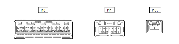
COMBINATION METER ASSEMBLY
(a) Measure the voltage, resistance and waveform according to the value(s) in the table below.
| Terminal No. (Symbol) | Wiring Color | Terminal Description | Condition | Specified Condition |
|---|---|---|---|---|
| I10-2 (MSM+) - Body ground | L - Body ground | Steering pad switch assembly signal | Power switch on (IG), enter, top and back switches on steering pad switch assembly not pushed | 4.8 to 5.2 V |
| Power switch on (IG), enter, top or back switches on steering pad switch assembly pushed | Below 1 V | |||
| I10-3 (MSTI) - Body ground | B - Body ground | Steering pad switch assembly signal | Power switch on (IG), up, down, right, and left switches on steering pad switch assembly not pushed | 4.8 to 5.2 V |
| Power switch on (IG), up, down, right, or left switches on steering pad switch assembly pushed | Below 1 V | |||
| I10-4 (ODO) - Body ground | G - Body ground | ODO/TRIP switch signal | Power switch on (IG), ODO/TRIP switch not pushed | 4 to 6 V |
| Power switch on (IG), ODO/TRIP switch pushed | Below 1 V | |||
| I10-5 (EPB) - Body ground | SB - Body ground | Parking brake switch signal | Power switch on (IG), parking brake switch is off | 11 to 14 V |
| Power switch on (IG), parking brake switch is on | Below 1.5 V | |||
| I10-9 (S) - Body ground | LG - Body ground | Engine oil pressure switch signal | "Low Oil Pressure Stop in a Safe Place See Owner's Manual" is displayed | Below 1 V |
| "Low Oil Pressure Stop in a Safe Place See Owner's Manual" is not displayed | 11 to 14 V | |||
| I10-15 (OILW) - Body ground | B - Body ground | Ground | Always | Below 1 Ω |
| I10-16 (WLVL) - Body ground | LG - Body ground | Washer fluid level signal | Power switch on (IG), washer fluid level not low | 11 to 14 V |
| Power switch on (IG), washer fluid level low | Below 1 V | |||
| I10-19 (+S) - Body ground | V - Body ground | Speed signal for other system (Output) | Driving at approximately 20 km/h (12 mph) | Pulse generation (See waveform 1) |
| I10-20 (SI) - Body ground | V - Body ground | Speed signal for other system (Input) | Driving at approximately 20 km/h (12 mph) | Pulse generation (See waveform 1) |
| I10-21 (IG+) - Body ground | B - Body ground | Power switch signal | Power switch off | Below 1 V |
| Power switch on (IG) | 11 to 14 V | |||
| I10-22 (B) - Body ground | Y - Body ground | Battery | Power switch off | 11 to 14 V |
| I10-25 (TR) - Body ground | V - Body ground | Trip switch signal | Power switch on (IG), up switch and down switch of trip switch not pushed | 4.6 to 5.3 V |
| Power switch on (IG), up switch of trip switch pushed | Below 1 V | |||
| Power switch on (IG), down switch of trip switch pushed | 2 to 3.6 V | |||
| I10-26 (SW3) - Body ground | P - Body ground | Trip switch signal | Always | Below 1 V |
| I10-27 (FR) - I10-28 (FE) | SB - GR | Fuel sender gauge signal | Power switch on (IG), fuel level F | Below 1 V |
| Power switch on (IG), fuel level E | 4.5 to 9 V | |||
| I10-29 (CANH) - Body ground | G - Body ground | CAN communication line | - | - |
| I10-30 (CANL) - Body ground | W - Body ground | CAN communication line | - | - |
| I10-31 (ES) - Body ground | W-B - Body ground | Ground | Always | Below 1 Ω |
| I10-39 (ILL-) - Body ground | P - Body ground | Illumination signal | Power switch on (IG), headlight dimmer switch off | 11 to 14 V |
| Power switch on (IG), headlight dimmer switch in tail or head position | Below 1 V | |||
| I10-40 (EP) - Body ground | W-B - Body ground | Ground | Always | Below 1 Ω |
| I11-1 (B) - Body ground | L - Body ground | Battery | Power switch off | 11 to 14 V |
| I11-2 (HZSW) - Body ground | B - Body ground | Hazard warning switch signal | Power switch on (IG), hazard warning switch not pressed | 11 to 14 V |
| Power switch on (IG), hazard warning switch pressed | Below 1 V | |||
| I11-3 (ER) - Body ground | L - Body ground | RH turn indicator light signal (Input) | Power switch on (IG), RH turn signal switch off | 11 to 14 V |
| Power switch on (IG), RH turn signal switch on | Below 1 V | |||
| I11-4 (EL) - Body ground | R - Body ground | LH turn indicator light signal (Input) | Power switch on (IG), LH turn signal switch off | 11 to 14 V |
| Power switch on (IG), LH turn signal switch on | Below 1 V | |||
| I11-5 (TRNR) - Body ground | SB - Body ground | RH turn indicator light signal (Output) | Power switch on (IG), RH turn indicator light off | Below 1 V |
| Power switch on (IG), RH turn indicator light blinking | 11 to 14 V ←→ Below 1 V | |||
| I11-6 (INT) - Body ground | LG - Body ground | Tire pressure warning reset switch | Power switch on (IG), tire pressure warning reset switch off | 8 to 15 V |
| Power switch on (IG), tire pressure warning reset switch on | Below 1 V | |||
| I11-7 (LR) - Body ground | L - Body ground | RH turn indicator light signal (Output) | Power switch on (IG), RH turn indicator light off | Below 1 V |
| Power switch on (IG), RH turn indicator light blinking | 11 to 14 V ←→ Below 1 V | |||
| I11-8 (SW) - Body ground | B - Body ground | Headlight dimmer switch assembly (full turn) signal | Headlight dimmer switch assembly on (full turn) | 11 to 14 V |
| Headlight dimmer switch assembly off | Below 1 V | |||
| I11-9 (MSCL) - Body ground | W - Body ground | CAN communication line | - | - |
| I11-10 (MSCH) - Body ground | R - Body ground | CAN communication line | - | - |
| I11-11 (TRNL) - Body ground | Y - Body ground | LH turn indicator light signal (Output) | Power switch on (IG), LH turn indicator light off | Below 1 V |
| Power switch on (IG), LH turn indicator light blinking | 11 to 14 V ←→ Below 1 V | |||
| I11-12 (HAZM) - Body ground | R - Body ground | Hazard warning signal switch signal (Output) | Power switch on (IG), hazard warning signal switch not pressed | Below 1 V |
| Power switch on (IG), hazard warning signal switch pressed | 11 to 14 V ←→ Below 1 V | |||
| I11-13 (LL) - Body ground | Y - Body ground | LH turn indicator light signal (Output) | Power switch on (IG), LH turn indicator light off | Below 1 V |
| Power switch on (IG), LH turn indicator light blinking | 11 to 14 V ←→ Below 1 V |
(1) Using an oscilloscope, check waveform 1.
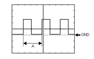 Waveform 1 (Reference)
 | Item | Condition |
|---|---|
| Tester Connection | |
| Tool setting | 5 V/DIV., 20 ms./DIV. |
| Vehicle condition | Driving at approximately 20 km/h (12 mph) |
HINT:
When the system is functioning normally, one wheel revolution generates 4 pulses. As the vehicle speed increases, the width indicated by (A) in the illustration narrows.
READ NEXT:
 Dtc Check / Clear
DTC CHECK / CLEAR CHECK DTC (a) Connect the Techstream to the DLC3. (b) Turn the power switch on (IG). (c) Turn the Techstream on. (d) Enter the following menus: Body Electrical / Combination Meter /
Freeze Frame Data
FREEZE FRAME DATA FREEZE FRAME DATA (a) Whenever a meter DTC is detected, the combination meter assembly stores the current vehicle state as freeze frame data. CHECK FREEZE FRAME DATA (a) Connect the
Data List / Active Test
DATA LIST / ACTIVE TEST DATA LIST NOTICE: In the table below, the values listed under "Normal Condition" are reference values. Do not depend solely on these reference values when deciding whether a pa
SEE MORE:
Fuel Pressure Regulator
ComponentsCOMPONENTS ILLUSTRATION *1 FUEL PRESSURE REGULATOR ASSEMBLY *2 FUEL PUMP ASSEMBLY WITH FILTER *3 NO. 1 FUEL SUB-TANK *4 NO. 1 FUEL SUCTION SUPPORT *5 FUEL SUCTION PLATE SUB-ASSEMBLY *6 NO. 2 FUEL TANK CUSHION *7 NO. 3 FUEL TANK CUSHION *8 FUEL PUMP
Freeze Frame Data
FREEZE FRAME DATA FREEZE FRAME DATA/INFORMATION (a) Using the Techstream, check the vehicle condition (ECU, sensor) when the brake system operates or a DTC is output. (b) The freeze frame data that is recorded when a DTC is stored can be used to check the INF codes, but only for DTCs which can be st
© 2016-2026 Copyright www.lexunx.com
