Lexus NX: Inspection
INSPECTION
PROCEDURE
1. INSPECT CAMSHAFT TIMING OIL CONTROL VALVE ASSEMBLY
(a) Measure the resistance according to the value(s) in the table below.
Standard Resistance:
| Tester Connection | Condition | Specified Condition |
|---|---|---|
| 1 - 2 | 20°C (68°F) | 6.9 to 7.9 Ω |
If the result is not as specified, replace the camshaft timing oil control valve assembly.
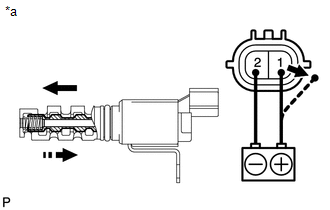
| (b) Connect the battery positive (+) lead to terminal 1 and negative (-) lead to terminal 2 and check the movement of the valve. OK:
If the result is not as specified, replace the camshaft timing oil control valve assembly. If the valve cannot return properly because of foreign matter, a small pressure leak in the advanced direction may occur and a DTC may be stored. |
|
READ NEXT:
 Installation
INSTALLATION PROCEDURE 1. INSTALL CAMSHAFT TIMING OIL CONTROL VALVE ASSEMBLY (a) Apply a light coat of engine oil to a new O-ring and install the O-ring to the camshaft timing oil control valve assemb
Camshaft Position Sensor
ComponentsCOMPONENTS ILLUSTRATION *1 CAMSHAFT POSITION SENSOR *2 NO. 1 ENGINE COVER SUB-ASSEMBLY N*m (kgf*cm, ft.*lbf) : Specified torque Toyota Genuine Adhesive 1324, Three Bon
Crankshaft Position Sensor
ComponentsCOMPONENTS ILLUSTRATION *1 CRANKSHAFT POSITION SENSOR - - N*m (kgf*cm, ft.*lbf) : Specified torque Toyota Genuine Adhesive 1324, Three Bond 1324 or equivalent ★
SEE MORE:
STSW Monitor Malfunction (B2275)
DESCRIPTION This DTC is stored when a malfunction is detected in the starter circuit inside the certification ECU (smart key ECU assembly). DTC No. Detection Item DTC Detection Condition Trouble Area Note B2275 STSW Monitor Malfunction Certification ECU (smart key ECU assembly) in
Software Incompatibility with Body Control Module Invalid/Incompatible Software Component (U032257)
DESCRIPTION If the vehicle information stored in the forward recognition camera does not match the vehicle information sent from the main body ECU (multiplex network body ECU), the forward recognition camera stores DTC U032257. DTC No. Detection Item DTC Detection Condition Trouble Area D
