Lexus NX: Terminals Of Ecu
TERMINALS OF ECU
CHECK FRONT POWER SEAT SWITCH LH

(a) Disconnect the g11 and g12 front power seat switch LH connectors.
(b) Measure the voltage and resistance according to the value(s) in the table below.
| Tester Connection | Wiring Color | Terminal Description | Condition | Specified Condition |
|---|---|---|---|---|
| g11-2 (GND) - Body ground | W-B - Body ground | Ground | Always | Below 1 Ω |
| g11-7 (+B) - Body ground | W - Body ground | Battery power supply | Power switch off | 11 to 14 V |
| g12-12 (SYSB) - Body ground | P - Body ground | System power source | Power switch off | 11 to 14 V |
| g12-3 (IG) - Body ground | P - Body ground | IG power supply | Power switch on (IG) | 11 to 14 V |
| Power switch off | Below 1 V | |||
| g12-10 (DBCL) - Body ground | GR - Body ground | Driver seat belt buckle switch signal | Driver seat belt fastened | Below 1 Ω |
| Driver seat belt unfastened | 10 kΩ or higher |
(c) Reconnect the g11 and g12 front power seat switch LH connectors.
(d) Measure the voltage and resistance according to the value(s) in the table below.
| Tester Connection | Wiring Color | Terminal Description | Condition | Specified Condition |
|---|---|---|---|---|
| g11-6 (+B2) - Body ground | SB - Body ground | Lumbar support adjuster power source | Power switch off | 11 to 14 V |
| g11-1 (GND2) - Body ground | W-B - Body ground | Lumbar support adjuster ground | Always | Below 1 Ω |
| g11-3 (SLD+) - Body ground | L - Body ground | Slide motor signal (forward) | Slide switch off | Below 1 V |
| Slide switch on (Forward) | 11 to 14 V | |||
| g11-4 (SLD-) - Body ground | GR - Body ground | Slide motor signal (rearward) | Slide switch off | Below 1 V |
| Slide switch on (Rearward) | 11 to 14 V | |||
| g11-5 (FRV-) - Body ground | R - Body ground | Front vertical motor signal (downward) | Front vertical switch off | Below 1 V |
| Front vertical switch on (Downward) | 11 to 14 V | |||
| g11-8 (FRV+) - Body ground | B - Body ground | Front vertical motor signal (upward) | Front vertical switch off | Below 1 V |
| Front vertical switch on (Upward) | 11 to 14 V | |||
| g11-9 (RCL+) - Body ground | P - Body ground | Reclining motor signal (forward) | Reclining switch off | Below 1 V |
| Reclining switch on (Forward) | 11 to 14 V | |||
| g11-11 (RCL-) - Body ground | LG - Body ground | Reclining motor signal (rearward) | Reclining switch off | Below 1 V |
| Reclining switch on (Rearward) | 11 to 14 V | |||
| g11-10 (LFT+) - Body ground | V - Body ground | Rear lifter motor signal (upward) | Rear lifter switch off | Below 1 V |
| Rear lifter switch on (Upward) | 11 to 14 V | |||
| g11-12 (LFT-) - Body ground | G - Body ground | Rear lifter motor signal (downward) | Rear lifter switch off | Below 1 V |
| Rear lifter switch on (Downward) | 11 to 14 V | |||
| g12-1 (SGND) - Body ground | BR - Body ground | Position sensor ground | Always | Below 1 Ω |
| g12-5 (SSRS) - g12-1 (SGND) | G- BR | Slide position signal | Slide function operating | 4.8 to 5.1 V |
CHECK OUTER MIRROR CONTROL ECU ASSEMBLY (for Driver Side)
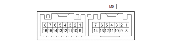
(a) Disconnect the M5 outer mirror control ECU assembly (for Driver Side) connector.
(b) Measure the voltage and resistance according to the value(s) in the table below.
| Tester Connection | Wiring Color | Terminal Description | Condition | Specified Condition |
|---|---|---|---|---|
| M5-5 (SIG) - Body ground | GR - Body ground | IG power supply | Power switch on (IG) | 11 to 14 V |
| Power switch off | Below 1 V | |||
| M5-6 (CPUB) - Body ground | GR - Body ground | Battery power supply | Power switch off | 11 to 14 V |
| M5-7 (GND) - Body ground | W-B - Body ground | Ground | Always | Below 1 Ω |
| M5-14 (BDR) - Body ground | Y - Body ground | Battery power supply | Power switch off | 11 to 14 V |
(c) Reconnect the M5 outer mirror control ECU assembly (for Driver Side) connector.
(d) Measure the voltage according to the value(s) in the table below.
| Tester Connection | Wiring Color | Terminal Description | Condition | Specified Condition |
|---|---|---|---|---|
| M5-1 (MM) - M5-7 (GND) | L - W-B | SET switch signal for seat memory switch | SET switch on | Below 1 V |
| SET switch off | 11 to 14 V | |||
| M5-2 (M1) - M5-7 (GND) | G - W-B | M1 switch signal for seat memory switch | M1 switch on | Below 1 V |
| M1 switch off | 11 to 14 V | |||
| M5-3 (M2) - M5-7 (GND) | P - W-B | M2 switch signal for seat memory switch | M2 switch on | Below 1 V |
| M2 switch off | 11 to 14 V | |||
| M5-4 (M3) - M5-7 (GND) | B - W-B | M3 switch signal for seat memory switch | M3 switch on | Below 1 V |
| M3 switch off | 11 to 14 V |
READ NEXT:
 Diagnosis System
DIAGNOSIS SYSTEM DESCRIPTION (a) Front power seat control system (w/ Memory) data and Diagnostic Trouble Codes (DTCs) can be read through the Data Link Connector 3 (DLC3) of the vehicle. When the syst
Dtc Check / Clear
DTC CHECK / CLEAR CHECK DTC (a) Connect the Techstream to the DLC3. (b) Turn the power switch on (IG). (c) Turn the Techstream on. (d) Enter the following menus: Body Electrical / Driver Seat / Troubl
Data List / Active Test
DATA LIST / ACTIVE TEST DATA LIST HINT: Using the Techstream to read the Data List allows the values or states of switches, sensors, actuators and other items to be read without removing any parts. Th
SEE MORE:
Rear Seat Belt Warning Light Malfunction
DESCRIPTION The main body ECU (multiplex network body ECU) detects whether either rear door is open or closed based on the condition of the left and right courtesy light switches and then sends the rear door status signal to the combination meter assembly. The combination meter assembly detects the
Installation
INSTALLATION PROCEDURE 1. INSTALL STEREO COMPONENT EQUALIZER ASSEMBLY (a) Install the stereo component equalizer assembly with 2 nuts. 2. INSTALL STEREO COMPONENT EQUALIZER ASSEMBLY WITH BRACKET (a) Connect all the connectors and temporarily install the stereo component equalizer assembly by atta
