- Power switch on (IG)
- Seat heater switch (for Front Passenger Side) on
Lexus NX: Terminals Of Ecu
TERMINALS OF ECU
CHECK AIR CONDITIONING AMPLIFIER ASSEMBLY
.png)
(a) Disconnect the I50 air conditioning amplifier assembly connector.
(b) Measure the voltage and resistance according to the value(s) in the table below.
| Tester Connection | Wiring Color | Terminal Description | Condition | Specified Condition |
|---|---|---|---|---|
| I50-1 (IG+) - Body ground | SB - Body ground | IG power supply | Power switch on (IG) | 11 to 14 V |
| Power switch off | Below 1 V | |||
| I50-14 (GND) - Body ground | W-B - Body ground | Ground | Always | Below 1 Ω |
| I50-21 (B) - Body ground | GR - Body ground | Battery power supply | Power switch off | 11 to 14 V |
(c) Reconnect the I50 air conditioning amplifier assembly connector.
(d) Measure the voltage and resistance according to the value(s) in the table below.
(e) Check for pulse generation according to the value(s) in the table below.
| Tester Connection | Wiring Color | Terminal Description | Condition | Specified Condition |
|---|---|---|---|---|
| I50-16 (SHP+) - Body ground | V - Body ground | Seat heater (for Front Passenger Side) drive signal | | Below 1 V |
| I50-17 (SHD+) - Body ground | LG - Body ground | Seat heater (for Driver Side) input signal |
| Below 1 V |
| I50-18 (SHPE) - Body ground* | GR - Body ground | Seat heater (for Rear RH) input signal |
| Below 1 V |
| I50-36 (SHDE) - Body ground* | LG - Body ground | Seat heater (for Rear LH) input signal |
| Below 1 V |
| I50-37 (LIN1) - Body ground | B - Body ground | Seat heater switch signal | Power switch on (IG) | Pulse generation |
| I54-3 (TSR) - I54-7 (SG-3) | P - R | Seat heater sensor (for Front Passenger Side) input signal | Engine switch off (0 to 30°C [32 to 86°F]) |
|
| I54-4 (TSL) - I54-8 (SG-6) | W - G | Seat heater sensor (for Driver Side) input signal | Engine switch off (0 to 30°C [32 to 86°F]) |
|
| I54-5 (TFAR) - I54-23 (SG-7)* | R - W | Seat heater sensor (for Rear RH) input signal | Engine switch off (0 to 30°C [32 to 86°F]) |
|
| I54-7 (SG-3) - Body ground | R - Body ground | Ground for seat heater sensor (for Front Passenger Side) | Always | Below 1 Ω |
| I54-8 (SG-6) - Body ground | G - Body ground | Ground for seat heater sensor (for Driver Side) | Always | Below 1 Ω |
| I54-20 (TFAL) - I54-23 (SG-7)* | G - W | Seat heater sensor (for Rear LH) input signal | Engine switch off (0 to 30°C [32 to 86°F]) |
|
| I54-16 (RLIN) - Body ground* | V - Body ground | Refreshing seat switch signal (LIN) | Power switch on (IG) | Pulse generation (See waveform) |
| I54-23 (SG-7) - Body ground* | W - Body ground | Ground for seat heater sensor (for Rear LH and RH) | Always | Below 1 Ω |
- *: w/ Rear Seat Heater
(f) Wavefrom:
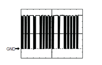
| Item | Content |
|---|---|
| Terminal No. | I54-16 (RLIN) - Body ground* |
| Tool Setting | 2 V/DIV., 20 μs/DIV. |
| Vehicle Condition | Power switch on (IG) |
- *: w/ Rear Seat Heater
CHECK AIR CONDITIONING CONTROL ASSEMBLY
Click here .gif)
READ NEXT:
 Diagnosis System
DIAGNOSIS SYSTEM DESCRIPTION (a) Seat heater system data and Diagnostic Trouble Codes (DTCs) can be read through the Data Link Connector 3 (DLC3) of the vehicle. When the system seems to be malfunctio
Dtc Check / Clear
DTC CHECK / CLEAR CHECK DTC (a) Connect the Techstream to the DLC3. (b) Turn the power switch on (IG). (c) Turn the Techstream on. (d) Enter the following menus: Body Electrical / Air Conditioner / Tr
Data List / Active Test
DATA LIST / ACTIVE TEST DATA LIST HINT: Using the Techstream to read the Data List allows the values or states of switches, sensors, actuators and other items to be read without removing any parts. Th
SEE MORE:
Vehicle Control History
VEHICLE CONTROL HISTORY NOTICE: Make sure to record any output Vehicle Control History codes before clearing them and checking the Vehicle Control History again. CHECK VEHICLE CONTROL HISTORY (ROAD SIGN ASSIST SYSTEM) (a) Connect the Techstream to the DLC3. (b) Turn the power switch on (IG). (c) Tur
Components
COMPONENTS ILLUSTRATION *A for Compact Spare Tire *B for Full Size Spare Tire *1 DECK FLOOR BOX LH *2 NO. 3 DECK BOARD SUB-ASSEMBLY *3 REAR DECK FLOOR BOX *4 NEGATIVE AUXILIARY BATTERY TERMINAL N*m (kgf*cm, ft.*lbf): Specified torque - - ILLUSTRATION *
© 2016-2026 Copyright www.lexunx.com
