- Power switch off
- All doors closed
- Electrical key transmitter sub-assembly not inside vehicle
-
All doors locked through wireless operation
(electrical key transmitter sub-assembly brought inside detection area*1)
Lexus NX: Terminals Of Ecu
TERMINALS OF ECU
CHECK CERTIFICATION ECU (SMART KEY ECU ASSEMBLY)
.png)
(a) Disconnect the I53 certification ECU (smart key ECU assembly) connector.
(b) Measure the voltage and resistance according to the value(s) in the table below.
| Tester Connection | Input/Output | Wiring Color | Terminal Description | Condition | Specified Condition | Related Data List Item |
|---|---|---|---|---|---|---|
| I53-11 (E) - Body ground | - | W-B - Body ground | Ground | Always | Below 1 Ω | - |
| I53-10 (+B) - I53-11 (E) | Input | W - W-B | Power supply | Power switch off | 11 to 14 V | - |
(c) Reconnect the I53 certification ECU (smart key ECU assembly) connector.
(d) Measure the voltage and check for pulses according to the value(s) in the table below.
| Tester Connection | Input/Output | Wiring Color | Terminal Description | Condition | Specified Condition | Related Data List Item |
|---|---|---|---|---|---|---|
| I51-3 (IG1D) - I53-11 (E) | Output | W - W-B | IG power supply | Power switch off → on (IG) | Below 1 V → 11 to 14 V | - |
| I53-4 (CLG1) - I53-11 (E) | Output | R - W-B | Output to driver door electrical key antenna (request signal (challenge) is sent to door electrical key antenna from certification ECU (smart key ECU assembly) to form detection area) | Procedure: | Pulse generation (See waveform 1) | Overhead + Driver Side (key diagnostic mode) |
| Procedure:
| Pulse generation (See waveform 2) | |||||
| I53-4 (CLG1) - I53-11 (E) | Input | R - W-B | Input to driver door lock sensor (front door outside handle assembly (for driver door) lock sensor on signal is sent to the certification ECU (smart key ECU assembly)) | Procedure:
| Pulse generation (See waveform 10) | D-Door Trigger Switch |
| I53-4 (CLG1) - I53-11 (E) | Input | R - W-B | Input to driver door unlock sensor (when system is in unlock standby mode and unlock sensor is touched, door electrical key antenna sends unlock sensor input signal (sensing) to certification ECU (smart key ECU assembly)) | Procedure:
| Pulse generation (See waveform 11) | D-Door Touch Sensor |
| I53-3 (CG1B) - I53-11 (E) | Output | W - W-B | Output to driver door electrical key antenna (terminal on opposite side of component from CLG1 output terminal) | Procedure:
| Pulse generation (See waveform 3) | Overhead + Driver Side (key diagnostic mode) |
| Procedure:
| Pulse generation (See waveform 4) | |||||
| I53-2 (CLG2) - I53-11 (E) | Output | G - W-B | Output to front passenger door electrical key antenna (request signal (challenge) is sent to door electrical key antenna from certification ECU (smart key ECU assembly) to form detection area) | Procedure:
| Pulse generation (See waveform 1) | Overhead + Passenger Side (key diagnostic mode) |
| Procedure:
| Pulse generation (See waveform 2) | |||||
| I53-2 (CLG2) - I53-11 (E) | Input | G - W-B | Input to front passenger door lock sensor (front door outside handle assembly (for front passenger door) lock sensor on signal is sent to the certification ECU (smart key ECU assembly)) | Procedure:
| Pulse generation (See waveform 10) | P-Door Trigger Switch |
| I53-2 (CLG2) - I53-11 (E) | Input | G - W-B | Input to front passenger door unlock sensor (when system is in unlock standby mode and unlock sensor is touched, door electrical key antenna sends unlock sensor input signal (sensing) to certification ECU (smart key ECU assembly)) | Procedure:
| Pulse generation (See waveform 11) | P-Door Touch Sensor |
| I53-1 (CG2B) - I53-11 (E) | Output | W - W-B | Output to front passenger door electrical key antenna (terminal on opposite side of component from CLG2 output terminal) | Procedure:
| Pulse generation (See waveform 3) | Overhead + Passenger Side (key diagnostic mode) |
| Procedure:
| Pulse generation (See waveform 4) | |||||
| I52-8 (CLG3) - I53-11 (E) | Output | W - W-B | Output to rear door electrical key antenna (for driver side) (request signal (challenge) is sent to door electrical key antenna from certification ECU (smart key ECU assembly) to form detection area) | Procedure:
| Pulse generation (See waveform 1) | Overhead + Driver Side Rear (key diagnostic mode) |
| Procedure:
| Pulse generation (See waveform 2) | |||||
| I52-8 (CLG3) - I53-11 (E) | Input | W - W-B | Input to rear door lock sensor (for driver side) (rear door outside handle assembly (for driver side) lock sensor on signal is sent to the certification ECU (smart key ECU assembly)) | Procedure:
| Pulse generation (See waveform 10) | Dr-Door Trigger Switch |
| I52-8 (CLG3) - I53-11 (E) | Input | W - W-B | Input to rear door unlock sensor (for driver side) (when system is in unlock standby mode and unlock sensor is touched, door electrical key antenna sends unlock sensor input signal (sensing) to certification ECU (smart key ECU assembly)) | Procedure:
| Pulse generation (See waveform 11) | Dr-Door Touch Sensor |
| I52-7 (CG3B) - I53-11 (E) | Output | V - W-B | Output to rear door (for driver side) electrical key antenna (terminal on opposite side of component from CLG3 output terminal) | Procedure:
| Pulse generation (See waveform 3) | Overhead + Driver Side Rear (key diagnostic mode) |
| Procedure:
| Pulse generation (See waveform 4) | |||||
| I52-10 (CLG4) - I53-11 (E) | Output | W - W-B | Output to rear door electrical key antenna (for front passenger side) (request signal (challenge) is sent to door electrical key antenna from certification ECU (smart key ECU assembly) to form detection area) | Procedure:
| Pulse generation (See waveform 1) | Overhead + Passenger Side Rear (key diagnostic mode) |
| Procedure:
| Pulse generation (See waveform 2) | |||||
| I52-10 (CLG4) - I53-11 (E) | Input | W - W-B | Input to rear door lock sensor (for front passenger side) (rear door outside handle assembly (for front passenger side) lock sensor on signal is sent to the certification ECU (smart key ECU assembly)) | Procedure:
| Pulse generation (See waveform 10) | Pr-Door Trigger Switch |
| I52-10 (CLG4) - I53-11 (E) | Input | W - W-B | Input to rear door unlock sensor (for front passenger side) (when system is in unlock standby mode and unlock sensor is touched, door electrical key antenna sends unlock sensor input signal (sensing) to certification ECU (smart key ECU assembly)) | Procedure:
| Pulse generation (See waveform 11) | Pr-Door Touch Sensor |
| I52-9 (CG4B) - I53-11 (E) | Output | L - W-B | Output to rear door (for front passenger side) electrical key antenna (terminal on opposite side of component from CLG4 output terminal) | Procedure:
| Pulse generation (See waveform 3) | Overhead + Passenger Side Rear (key diagnostic mode) |
| Procedure:
| Pulse generation (See waveform 4) | |||||
| I53-21 (CLG5) - I53-11 (E) | Output | R - W-B | Output to No. 1 indoor electrical key antenna assembly (front floor) | Procedure:
| Pulse generation (See waveform 5) | Overhead + Front Room (key diagnostic mode) |
| I53-20 (CG5B) - I53-11 (E) | Output | G - W-B | Output to No. 1 indoor electrical key antenna assembly (front floor) (terminal on opposite side of component from CLG5 output terminal) | Procedure:
| Pulse generation (See waveform 5) | Overhead + Front Room (key diagnostic mode) |
| I52-5 (TSW5) - I53-11 (E) | Input | Y - W-B | Back door opener switch assembly (open switch) signal input | Back door opener switch assembly (open switch) off → on | Pulse generation (See waveform 7) | Tr/B-Door Unlock SW |
| I52-13 (TSW6) - I53-11 (E) | Input | L - W-B | Back door opener switch assembly (lock switch) signal input | Back door opener switch assembly (lock switch) off → on | Pulse generation (See waveform 7) | Tr/B-Door Lock SW |
| I52-15 (CLG6) - I53-11 (E) | Output | W - W-B | Output to No. 2 indoor electrical key antenna assembly (rear floor) | Procedure:
| Pulse generation (See waveform 5) | Overhead + Rear Room (key diagnostic mode) |
| I52-14 (CG6B) - I53-11 (E) | Output | B - W-B | Output to No. 2 indoor electrical key antenna assembly (rear floor) (terminal on opposite side of component from CLG6 output terminal) | Procedure:
| Pulse generation (See waveform 5) | Overhead + Rear Room (key diagnostic mode) |
| I52-4 (CLG7) - I53-11 (E) | Output | W - W-B | Output to No. 3 indoor electrical key antenna assembly (inside luggage) | Procedure:
| Pulse generation (See waveform 5) | Overhead + Back Door (inside) (key diagnostic mode) |
| I52-3 (CG7B) - I53-11 (E) | Output | LG - W-B | Output to No. 3 indoor electrical key antenna assembly (inside luggage) (terminal on opposite side of component from CLG7 output terminal) | Procedure:
| Pulse generation (See waveform 5) | Overhead + Back Door (inside) (key diagnostic mode) |
| I52-18 (RCO) - I53-11 (E) | Output | R - W-B | Output to door control receiver (Power supply for door control receiver. Certification ECU (smart key ECU assembly) outputs 5 V when receiver starts operating.) | Procedure:
| Pulse generation (See waveform 8) | - |
| I52-19 (CSEL) - I53-11 (E) | Output | B - W-B | Communication channel switching circuit | Procedure:
| Below 1 V → pulse generation | - |
| I52-20 (RDAM) - I53-11 (E) | Input | L - W-B | Door control receiver verifies data received from electrical key transmitter sub-assembly. Door control receiver sends data from electrical key transmitter sub-assembly to certification ECU (smart key ECU assembly) (Door control receiver intermittently grounds 12 V signal from certification ECU (smart key ECU assembly)). | Proceed:
| Pulse generation (See waveform 9) | - |
| I52-21 (ASEL) - I53-11 (E)*2 | Output | LG - W-B | Output to wireless charger system | Procedure:
| Below 1 V → 4.5 to 6 V (For 1 second after power switch on (ACC)) | - |
| I52-2 (CLG8) - I53-11 (E) | Output | B - W-B | Output to electrical key antenna (outside luggage compartment) | Procedure:
| Pulse generation (See waveform 6) | Overhead + Back Door (key diagnostic mode) |
| I52-1 (CG8B) - I53-11 (E) | Output | W - W-B | Output to electrical key antenna (outside luggage compartment) (terminal on opposite side of component from CLG8 output terminal) | Procedure:
| Pulse generation (See waveform 6) | Overhead + Back Door (key diagnostic mode) |
-
*1: For details about the entry function detection area, refer to Operation Check.
Click here
.gif)
- *2: w/ Wireless Charging System
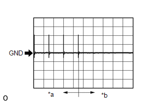
(e) Using an oscilloscope, check waveform 1.
NOTICE:
The oscilloscope waveform shown in the illustration is an example for reference only. Noise, chattering, etc. are not shown.
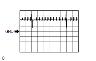 Waveform 1 (Reference)
 | Item | Content |
|---|---|
| Tester Connection | I53-4 (CLG1) - I53-11 (E) I53-2 (CLG2) - I53-11 (E) I52-8 (CLG3) - I53-11 (E) I52-10 (CLG4) - I53-11 (E) |
| Tool Setting | 5 V/DIV., 500 ms/DIV. |
| Condition | Procedure:
|
-
*: For details about the entry function detection area, refer to Operation Check.
Click here
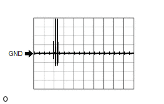
(f) Using an oscilloscope, check waveform 2.
NOTICE:
The oscilloscope waveform shown in the illustration is an example for reference only. Noise, chattering, etc. are not shown.
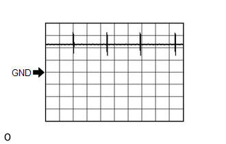 Waveform 2 (Reference)
 | Item | Content |
|---|---|
| Tester Connection | I53-4 (CLG1) - I53-11 (E) I53-2 (CLG2) - I53-11 (E) I52-8 (CLG3) - I53-11 (E) I52-10 (CLG4) - I53-11 (E) |
| Tool Setting | 5 V/DIV., 100 ms/DIV. |
| Condition | Procedure:
|
-
*: For details about the entry function detection area, refer to Operation Check.
Click here
(g) Using an oscilloscope, check waveform 3.
NOTICE:
The oscilloscope waveform shown in the illustration is an example for reference only. Noise, chattering, etc. are not shown.
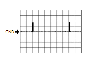 Waveform 3 (Reference)
 | Item | Content |
|---|---|
| Tester Connection | I53-3 (CG1B) - I53-11 (E) I53-1 (CG2B) - I53-11 (E) I52-7 (CG3B) - I53-11 (E) I52-9 (CG4B) - I53-11 (E) |
| Tool Setting | 5 V/DIV., 500 ms/DIV. |
| Condition | Procedure:
|
-
*: For details about the entry function detection area, refer to Operation Check.
Click here
(h) Using an oscilloscope, check waveform 4.
NOTICE:
The oscilloscope waveform shown in the illustration is an example for reference only. Noise, chattering, etc. are not shown.
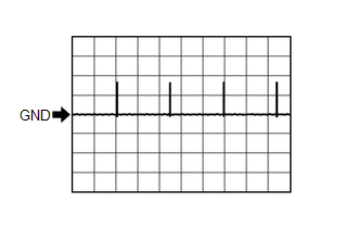 Waveform 4 (Reference)
 | Item | Content |
|---|---|
| Tester Connection | I53-3 (CG1B) - I53-11 (E) I53-1 (CG2B) - I53-11 (E) I52-7 (CG3B) - I53-11 (E) I52-9 (CG4B) - I53-11 (E) |
| Tool Setting | 5 V/DIV., 100 ms/DIV. |
| Condition | Procedure:
|
-
*: For details about the entry function detection area, refer to Operation Check.
Click here
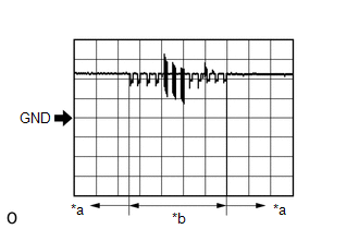
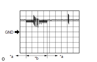
(i) Using an oscilloscope, check waveform 5
NOTICE:
The oscilloscope waveform shown in the illustration is an example for reference only. Noise, chattering, etc. are not shown.
| *a | For 30 seconds after closing any door using the door outside handle |
| *b | 30 seconds or more have elapsed after closing any door using the door outside handle |
| Item | Content |
|---|---|
| Tester Connection | I53-21 (CLG5) - I53-11 (E) I53-20 (CG5B) - I53-11 (E) I52-15 (CLG6) - I53-11 (E) I52-14 (CG6B) - I53-11 (E) I52-4 (CLG7) - I53-11 (E) I52-3 (CG7B) - I53-11 (E) |
| Tool Setting | 2 V/DIV., 500 ms/DIV. |
| Condition | Procedure:
|
(j) Using an oscilloscope, check waveform 6.
NOTICE:
The oscilloscope waveform shown in the illustration is an example for reference only. Noise, chattering, etc. are not shown.
 Waveform 6 (Reference)
 | Item | Content |
|---|---|
| Tester Connection | I52-2 (CLG8) - I53-11 (E) I52-1 (CG8B) - I53-11 (E) |
| Tool Setting | 2 V/DIV., 500 ms/DIV. |
| Condition | Procedure:
|
(k) Using an oscilloscope, check waveform 7.
NOTICE:
The oscilloscope waveform shown in the illustration is an example for reference only. Noise, chattering, etc. are not shown.
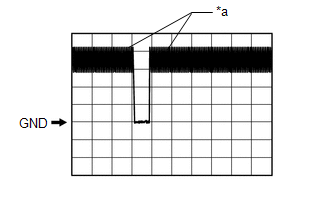
| *a | Checking for switch on signal at short intervals |
| Item | Content |
|---|---|
| Tester Connection | I52-5 (TSW5) - I53-11 (E) |
| Tool Setting | 2 V/DIV., 500 ms/DIV. |
| Condition | Back door opener switch assembly (open switch) off → on |
| Item | Content |
|---|---|
| Tester Connection | I52-13 (TSW6) - I53-11 (E) |
| Tool Setting | 2 V/DIV., 500 ms/DIV. |
| Condition | Back door opener switch assembly (lock switch) off → on |
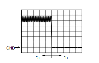
(l) Using an oscilloscope, check waveform 8.
NOTICE:
The oscilloscope waveform shown in the illustration is an example for reference only. Noise, chattering, etc. are not shown.
.png)
| *a | Before lock or unlock switch of electrical key transmitter sub-assembly pressed |
| *b | After lock or unlock switch of electrical key transmitter sub-assembly pressed |
| Item | Content |
|---|---|
| Tester Connection | I52-18 (RCO) - I53-11 (E) |
| Tool Setting | 2 V/DIV., 500 ms/DIV. |
| Condition | Procedure:
|
(m) Using an oscilloscope, check waveform 9.
NOTICE:
The oscilloscope waveform shown in the illustration is an example for reference only. Noise, chattering, etc. are not shown.
.png)
| *a | Before lock or unlock switch of electrical key transmitter sub-assembly pressed |
| *b | After lock or unlock switch of electrical key transmitter sub-assembly pressed |
| Item | Content |
|---|---|
| Tester Connection | I52-20 (RDAM) - I53-11 (E) |
| Tool Setting | 5 V/DIV., 500 ms/DIV. |
| Condition | Procedure:
|
(n) Using an oscilloscope, check waveform 10.
NOTICE:
The oscilloscope waveform shown in the illustration is an example for reference only. Noise, chattering, etc. are not shown.
| *a | Lock sensor not touched |
| *b | Lock sensor touched |
| Item | Content |
|---|---|
| Tester Connection | I53-4 (CLG1) - I53-11 (E) I53-2 (CLG2) - I53-11 (E) I52-8 (CLG3) - I53-11 (E) I52-10 (CLG4) - I53-11 (E) |
| Tool Setting | 5 V/DIV., 40 ms/DIV. |
| Condition | Procedure:
|
-
*: For details about the entry function detection area, refer to Operation Check.
Click here
(o) Using an oscilloscope, check waveform 11.
NOTICE:
The oscilloscope waveform shown in the illustration is an example for reference only. Noise, chattering, etc. are not shown.
| *a | Unlock sensor not touched |
| *b | Unlock sensor touched |
| Item | Content |
|---|---|
| Tester Connection | I53-4 (CLG1) - I53-11 (E) I53-2 (CLG2) - I53-11 (E) I52-8 (CLG3) - I53-11 (E) I52-10 (CLG4) - I53-11 (E) |
| Tool Setting | 5 V/DIV., 50 ms/DIV. |
| Condition | Procedure:
|
.png)
| *1 | Main Body ECU (Multiplex Network Body ECU) | - | - |
CHECK INSTRUMENT PANEL JUNCTION BLOCK ASSEMBLY AND MAIN BODY ECU (MULTIPLEX NETWORK BODY ECU)
(a) Remove the main body ECU (multiplex network body ECU) from the instrument panel junction block assembly.
Click here
(b) Measure the voltage and resistance according to the value(s) in the table below.
| Tester Connection | Input/Output | Wiring Color | Terminal Description | Condition | Specified Condition | Related Data List Item |
|---|---|---|---|---|---|---|
| A-11 (GND1) - Body ground | - | - | Ground | Always | Below 1 Ω | - |
| A-31 (BECU) - Body ground | Input | - | Battery power supply (for CPU) | Power switch off | 11 to 14 V | - |
| I48-6 (FLCY) - Body ground | Input | G - Body ground | Front door LH courtesy light switch input | Front door LH closed → open | 10 kΩ or higher → Below 1 Ω | FL Door Courtesy SW |
| I48-27 (FRCY) - Body ground | Input | W - Body ground | Front door RH courtesy light switch input | Front door RH closed → open | 10 kΩ or higher → Below 1 Ω | FR Door Courtesy SW |
| A-13 (LCTY) - Body ground | Input | - | Rear door LH courtesy light switch input | Rear door LH closed → open | 10 kΩ or higher → Below 1 Ω | RL Door Courtesy SW |
| A-2 (RCTY) - Body ground | Input | - | Rear door RH courtesy light switch input | Rear door RH closed → open | 10 kΩ or higher → Below 1 Ω | RR Door Courtesy SW |
| A-4 (BCTY) - Body ground | Input | - | Back door courtesy light switch input | Back door closed → open | 10 kΩ or higher → Below 1 Ω | Back Door Courtesy SW |
(c) Install the main body ECU (multiplex network body ECU) to the instrument panel junction block assembly.
Click here
(d) Measure the voltage and check for pulses according to the value(s) in the table below.
| Tester Connection | Input/Output | Wiring Color | Terminal Description | Condition | Specified Condition | Related Data List Item |
|---|---|---|---|---|---|---|
|
*1: w/ Power Seat
*2: w/o Power Seat | ||||||
| 4D-40 (LSFL) - Body ground | Input | B - Body ground | Front door LH unlock detection switch input | Front door LH locked → unlocked | Pulse generation (See waveform 1) | FL Door Lock Pos |
| 4D-39 (LSFR) - Body ground | Input | P - Body ground | Front door RH unlock detection switch input | Front door RH locked → unlocked | Pulse generation (See waveform 1) | FR Door Lock Pos |
| 4A-34 (LSWL) - Body ground | Input | Y - Body ground | Rear door LH unlock detection switch input | Rear door LH locked → unlocked | Pulse generation (See waveform 1) | RL-Door Lock Pos SW |
| I47-2 (LSWR) - Body ground | Input | Y - Body ground | Rear door RH unlock detection switch input | Rear door RH locked → unlocked | Pulse generation (See waveform 1) | RR-Door Lock Pos SW |
| I48-6 (FLCY) - Body ground | Input | G - Body ground | Front door LH courtesy light switch input | Front door LH closed → open | Pulse generation (See waveform 2) | FL Door Courtesy SW |
| I48-27 (FRCY) - Body ground | Input | W - Body ground | Front door RH courtesy light switch input | Front door RH closed → open | Pulse generation (See waveform 2) | FR Door Courtesy SW |
| 4A-18 (LCTY) - Body ground | Input | W - Body ground | Rear door LH courtesy light switch input | Rear door LH closed → open | Pulse generation (See waveform 2) | RL Door Courtesy SW |
| 4D-37 (RCTY) - Body ground | Input | Y - Body ground | Rear door RH courtesy light switch input | Rear door RH closed → open | Pulse generation (See waveform 2) | RR Door Courtesy SW |
| 4A-21 (BCTY) - Body ground | Input | LG - Body ground*1 R - Body ground*2 | Back door courtesy light switch input | Back door closed → opened | Pulse generation (See waveform 2) | Back Door Courtesy SW |
| 4B-52 (BZR) - Body ground | Output | P - Body ground | Wireless buzzer signal output | Procedure:
| Below 1 V → pulse generation | - |
(e) Using an oscilloscope, check waveform 1.
NOTICE:
The oscilloscope waveform shown in the illustration is an example for reference only. Noise, chattering, etc. are not shown.
Waveform 1 (Reference)| Item | Content |
|---|---|
| Tester Connection | 4D-40 (LSFL) - Body ground 4D-39 (LSFR) - Body ground 4A-34 (LSWL) - Body ground I47-2 (LSWR) - Body ground |
| Tool Setting | 2 V/DIV., 200 ms/DIV. |
| Condition | Door locked → unlocked |

| *a | Door locked |
| *b | Door unlocked |
(f) Using an oscilloscope, check waveform 2.
NOTICE:
The oscilloscope waveform shown in the illustration is an example for reference only. Noise, chattering, etc. are not shown.
Waveform 2 (Reference)| Item | Content |
|---|---|
| Tester Connection | I48-6 (FLCY) - Body ground I48-27 (FRCY) - Body ground 4A-18 (LCTY) - Body ground 4D-37 (RCTY) - Body ground 4A-21 (BCTY) - Body ground |
| Tool Setting | 2 V/DIV., 200 ms/DIV. |
| Condition | Door closed → opened |
| *a | Door closed |
| *b | Door open |
READ NEXT:
 Diagnosis System
DIAGNOSIS SYSTEM DESCRIPTION (a) Smart access system with push-button start (for Entry Function) data and Diagnostic Trouble Codes (DTCs) can be read through the vehicle Data Link Connector 3 (DLC3).
Dtc Check / Clear
DTC CHECK / CLEAR CHECK FOR DTC NOTICE: When using the Techstream with the power switch off, connect the Techstream to the DLC3 and turn a courtesy light switch on and off at intervals of 1.5 seconds
Data List / Active Test
DATA LIST / ACTIVE TEST DATA LIST NOTICE:
In the table below, the values listed under "Normal Condition" are reference values. Do not depend solely on these reference values when deciding whether a
SEE MORE:
Components
COMPONENTS ILLUSTRATION *1 DECK FLOOR BOX LH *2 NO. 3 DECK BOARD SUB-ASSEMBLY *3 REAR DECK FLOOR BOX *4 NEGATIVE AUXILIARY BATTERY TERMINAL N*m (kgf*cm, ft.*lbf): Specified torque - - ILLUSTRATION *1 BATTERY SERVICE HOLE COVER *2 HYBRID BATTERY SERVICE PLU
Accumulator Pressure Sensor (C1365)
DESCRIPTION The accumulator pressure sensor is built into the brake actuator (brake booster with master cylinder assembly). The skid control ECU (brake booster with master cylinder assembly) detects the accumulator pressure from the data sent from the accumulator pressure sensor, and then starts and
© 2016-2026 Copyright www.lexunx.com
