- The steering is unlocked.
- The power switch is off.
- The shift lever is in P.
Lexus NX: Terminals Of Ecu
TERMINALS OF ECU
CHECK CERTIFICATION ECU (SMART KEY ECU ASSEMBLY)
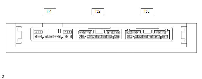
(a) Disconnect the I51 and I53 certification ECU (smart key ECU assembly) connectors.
(b) Measure the voltage and resistance according to the value(s) in the table below.
HINT:
Measure the values on the wire harness side with the connector disconnected.
| Tester Connection | Input/Output | Wiring Color | Terminal Description | Condition | Specified Condition | Related Data List Item |
|---|---|---|---|---|---|---|
| I51-2 (STP1) - Body ground | Input | B - Body ground | Stop light switch signal | Brake pedal depressed → Brake pedal released | 9 V or higher → 1 V or less | Stop Light Switch1 |
| I53-10 (+B) - I53-11 (E) | Input | W - W-B | Power source | Always | 11 to 14 V | - |
| I53-23 (SLP) - I53-11 (E) | Input | GR - W-B | Steering lock position signal | Steering locked | 10 kΩ or higher | Steering Unlock Switch |
| I53-22 (P) - I53-11 (E) | Input | B - W-B | P position signal | Shift lever in P → Shift lever not in P | 30 kΩ or higher → Below 200 Ω | Shift P Signal |
| I53-11 (E) - Body ground | - | W-B - Body ground | GND | Always | Below 1 Ω | - |
| I53-18 (SSW2) - Body ground | Input | G - Body ground | SSW2 contact signal HINT: Backup for SSW1. Behaves the same way as SSW1. | Power switch pushed → Power switch not pushed | Below 15 Ω → 10 kΩ or higher | Start Switch2 |
| I53-16 (SSW1) - Body ground | Input | LG - Body ground | SSW1 contact signal | Power switch pushed → Power switch not pushed | Below 15 Ω → 10 kΩ or higher | Start Switch1 |
| I53-9 (ACCD) - Body ground | Output | L - Body ground | ACC signal | 20°C (68°F) | 130.92 to 190.74 Ω | ACC Relay Monitor |
| I51-3 (IG1D) - Body ground | Output | W - Body ground | IG signal | 20°C (68°F) | 87.32 to 127.14 Ω | IG Relay Monitor (Outside) |
| I51-4 (CUTB) - I53-11 (E) | Input | P - W-B | Dark current cut pin*1 | Always | 11 to 14 V | - |
| I53-5 (SPD) - Body ground | Input | G - Body ground | Vehicle speed signal | Always | 30 kΩ or higher | Vehicle Speed Signal |
- *1: In order to prevent the vehicle auxiliary battery from being depleted when the vehicle is shipped long distances, a fuse that cuts unnecessary electrical load while the vehicle is being shipped is set in the circuit. If the fuse is removed, the circuit becomes open. If the fuse that is between the vehicle auxiliary battery and terminal CUTB is removed and the circuit is open, the certification ECU (smart key ECU assembly) changes to a certain control mode (example: the transmission of electric waves every 0.25 seconds that form the detection area stops).
(c) Reconnect the I53 and I51 certification ECU (smart key ECU assembly) connectors.
(d) Measure the voltage and check for pulses according to the value(s) in the table below.
| Tester Connection | Input/Output | Wiring Color | Terminal Description | Condition | Specified Condition | Related Data List Item |
|---|---|---|---|---|---|---|
| I51-2 (STP1) - I53-11 (E) | Input | B - W-B | Stop light switch signal | Brake pedal released → Brake pedal depressed | 1 V or less → 9 V or higher | Stop Light Switch1 |
| I53-23 (SLP) - I53-11 (E) | Input | GR - W-B | Steering lock position signal | Steering locked → Steering unlocked | 11 to 14 V → 1.5 V or less | Steering Unlock Switch |
| I53-24 (SLR+) - I53-11 (E) | Output | L - W-B | Steering lock motor operation command signal (Steering lock motor operation permission signal sent from the certification ECU (smart key ECU assembly)) | When a door is opened, the steering lock motor will be operated if all of the following conditions are met: | Pulse generation (See waveform 1) | - |
| I53-22 (P) - I53-11 (E) | Input | B - W-B | P position signal | Shift lever in P → Shift lever not in P | 9 V or higher → 2.76 V or less | Shift P Signal |
| I53-18 (SSW2) - I53-11 (E) | Input | G - W-B | SSW2 contact signal HINT: Backup for SSW1. Behaves the same way as SSW1. | Power switch not pushed → Power switch pushed | 9 V or higher → 1 V or less | Start Switch2 |
| I53-16 (SSW1) - I53-11 (E) | Input | LG - W-B | SSW1 contact signal | Power switch not pushed → Power switch pushed | 9 V or higher → 1 V or less | Start Switch1 |
| I53-9 (ACCD) - I53-11 (E) | Output | L - W-B | ACC signal | Power switch off → Power switch on (ACC) | 1 V or less → 8.5 V or higher | ACC Relay Monitor |
| I51-3 (IG1D) - I53-11 (E) | Output | W - W-B | IG signal | Power switch on (ACC) → Power switch on (IG) | 1 V or less → 9 V or higher | IG Relay Monitor (Outside) |
| I53-5 (SPD) - I53-11 (E) | Input | G - W-B | Vehicle speed signal | Vehicle being driven at approx. 5 km/h (3 mph) | Pulse generation (See waveform 2) | Vehicle Speed Signal |
| I51-12 (ST2) - I53-11 (E) | Output | LG - W-B | STSW signal | With the brake pedal depressed, the power switch is pressed and held → After approx. 3 sec. has elapsed, the power switch is released | 9 V or higher → 1 V or less | - |
HINT:
- The waveform of the steering lock actuator motor stopped can be checked without performing any particular operation.
-
The waveform of the steering lock actuator motor operating can be checked if either of the following operations is performed:
- To unlock the steering, bring the electrical key transmitter sub-assembly into the cabin and turn the power switch on (ACC) or on (IG).
- To lock the steering, open a door with the power switch off and the shift lever in P.
(e) Using an oscilloscope, check the waveform of the ECU.
NOTICE:
The oscilloscope waveform shown in the illustration is an example for reference only. Noise, chattering, etc. are not shown.
(1) Waveform 1
| Item | Content |
|---|---|
| Tester Connection | I53-24 (SLR+) - I53-11 (E) |
| Tool Setting | 2 V/DIV., 200 ms./DIV. |
| Condition | Steering lock motor stopped → Steering lock motor operating → Steering lock motor stopped |
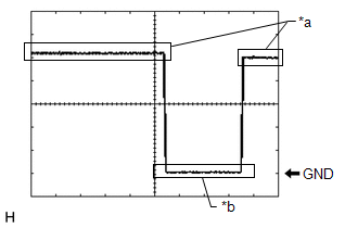
| *a | Steering lock motor not operating |
| *b | Steering lock motor operating |
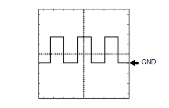
(2) Waveform 2
| Item | Content |
|---|---|
| Tester Connection | I53-5 (SPD) - I53-11 (E) |
| Tool Setting | 5 V/DIV., 200 ms./DIV. |
| Condition | Vehicle being driven at approx. 5 km/h (3 mph) |
HINT:
The wavelength becomes shorter as the vehicle speed increases.
CHECK STEERING LOCK ECU (STEERING LOCK ACTUATOR ASSEMBLY)
Click here .gif)
CHECK ID CODE BOX (IMMOBILISER CODE ECU)
Click here
CHECK POWER SWITCH
Click here
READ NEXT:
 Diagnosis System
DIAGNOSIS SYSTEM DESCRIPTION (a) Smart access system with push-button start (for Start Function) data and Diagnostic Trouble Codes (DTCs) can be read through the Data Link Connector 3 (DLC3) of the ve
Dtc Check / Clear
DTC CHECK / CLEAR NOTICE: When using the Techstream with the power switch off, connect the Techstream to the DLC3 and turn a courtesy light switch on and off at intervals of 1.5 seconds or less until
Diagnostic Trouble Code Chart
DIAGNOSTIC TROUBLE CODE CHART Smart Access System with Push-button Start (for Start Function) DTC No. Detection Item Link B2271 Ignition Hold Monitor Malfunction B2274 ACC Moni
SEE MORE:
Throttle / Pedal Position Sensor "A" Minimum Stop Performance (P2109)
DESCRIPTION The idle speed is controlled by the Electronic Throttle Control System (ETCS). The ETCS is comprised of a throttle actuator, which operates the throttle valve, and a throttle position sensor, which detects the opening amount of the throttle valve. The ECM controls the throttle actuator t
Side Camera Feedback Malfunction (C1683)
DESCRIPTION This DTC is stored if the parking assist ECU judges as a result of its self check that a synchronization problem is occurring in the image signal sent from the passenger side television camera assembly to the parking assist ECU. DTC No. Detection Item DTC Detection Condition Tro
© 2016-2026 Copyright www.lexunx.com
