Lexus NX: Test Mode Procedure
TEST MODE PROCEDURE
REAR BRAKE PAD REPLACEMENT MODE
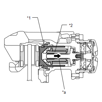
| *1 | Rear Disc Brake Piston |
| *2 | Nut |
| *a | Move nut back inside using pad replacement mode |
HINT:
When replacing the rear disc brake pad and rear disc, since the nut inside the rear disc brake cylinder assembly is in an advanced position, it is necessary to move the nut back inside the cylinder. The nut can be moved back using pad replacement mode.
(a) Pad replacement mode
- Turn the power switch off.
- Connect the Techstream to the DLC3.
- Turn the power switch on (IG) and the Techstream on.
-
Enter the following menus: Chassis / Electric Parking Brake / Utility / Check Mode.
NOTICE:
The parking brake must be released.
- Follow the Techstream display and select "Next".
-
Push and hold the electric parking brake switch (integration control and panel assembly) to the release side for 5 seconds or more.
NOTICE:
- Perform this procedure with the power switch on (IG).
- Make sure to perform this procedure with the brake pedal released.
- When the system changes to pad replacement mode, DTC C13A7 may be stored. If the DTC is stored, clear the DTCs after the procedure (rear brake pad replacement, etc.) is complete.
HINT:
When entering pad replacement mode, the parking brake indicator light (red) flashes (0.25 second intervals), and once the assembly finishes operating, the parking brake indicator light (red) flashes slowly (1 second intervals) (nut moves back inside the cylinder and system enters pad replacement mode).
| Tester Display |
|---|
| Check Mode |
- Turn the power switch off.
-
Using SST, connect terminals 12 (TS) and 4 (CG) of the DLC3.
SST:
09843-18040
NOTICE:
Do not connect the wrong terminals, as this will cause parts to be damaged.
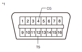
*1
DLC3
- Turn the power switch on (IG).
-
Within 8 seconds, operate the electric parking brake switch (integration control and panel assembly) to perform 3 on operations on the lock side (off (release) to on (pull)) and 3 on operations on the release side (off (release) to on (push)).
NOTICE:
If the operation is performed too quickly, the system may not respond. If the system does not respond, perform the operation again at a slower speed.
HINT:
The parking brake indicator light (red) flashes (0.25 second intervals).
-
Push and hold the electric parking brake switch (integration control and panel assembly) to the release side for 5 seconds or more.
NOTICE:
- Perform this procedure with the power switch on (IG).
- Make sure to perform this procedure with the brake pedal released.
- When the system changes to pad replacement mode, DTC C13A7 may be stored. If the DTC is stored, clear the DTCs after the procedure (rear brake pad replacement, etc.) is complete.
HINT:
After a short time passes, the parking brake actuator assembly operates, and once the assembly finishes operating, the parking brake indicator light (red) flashes slowly (1 second intervals) (nut moves back inside the cylinder and system enters pad replacement mode).
(b) Turn the power switch off.
NOTICE:
Do not operate the electric parking brake switch (integration control and panel assembly) until the procedures are complete. If operated, the system will return to its normal condition.
- Disconnect the Techstream from the DLC3.
- Disconnect SST from the DLC3.
(c) Normal condition recovery
(1) After the procedure (rear brake pad replacement, etc.) is complete, perform an electric parking brake switch (integration control and panel assembly) lock operation.
NOTICE:
- When performing work (replacing the rear brake pad, etc.), do not operate the electric parking brake switch (integration control and panel assembly) or turn the power switch on (IG) and operate the shift lever. If the electric parking brake switch (integration control and panel assembly) or shift lever is operated, the parking brake may operate and the rear disc brake piston may fall off. Also, make sure to disconnect the connector of the parking brake actuator assembly or disconnect the cable from the negative (-) auxiliary battery terminal.
- When DTC C13A7 is stored, clear the DTCs.
READ NEXT:
 Problem Symptoms Table
PROBLEM SYMPTOMS TABLE HINT:
Use the table below to help determine the cause of problem symptoms. If multiple suspected areas are listed, the potential causes of the symptoms are listed in order of
Dtc Check / Clear
DTC CHECK / CLEAR CHECK DTC AND FREEZE FRAME DATA (a) Turn the power switch off. (b) Connect the Techstream to the DLC3. (c) Turn the power switch on (IG) and the Techstream on. (d) Enter the followin
Freeze Frame Data
FREEZE FRAME DATA FREEZE FRAME DATA HINT:
If a DTC is output, the freeze frame data is recorded when the DTC occurs.
If freeze frame data is recorded when a DTC occurs, the freeze frame data is n
SEE MORE:
Disposal
DISPOSAL PROCEDURE 1. DISPOSE OF BRAKE BOOSTER PUMP ASSEMBLY (a) Remove the accumulator from the brake booster pump assembly. (b) Secure the accumulator in a vise. (c) Using a hacksaw, make a cut in the side of the accumulator within location (A) to release the high-pressure gas. Location Le
Steering Knuckle
ComponentsCOMPONENTS ILLUSTRATION *1 FRONT AXLE HUB SUB-ASSEMBLY LH *2 FRONT LOWER BALL JOINT ASSEMBLY LH *3 STEERING KNUCKLE LH *4 FRONT BRAKE DUST COVER N*m (kgf*cm, ft.*lbf): Specified torque ● Non-reusable part RemovalREMOVAL CAUTION / NOTICE / HINT HINT:
