Lexus NX: Thermostat
Components
COMPONENTS
ILLUSTRATION
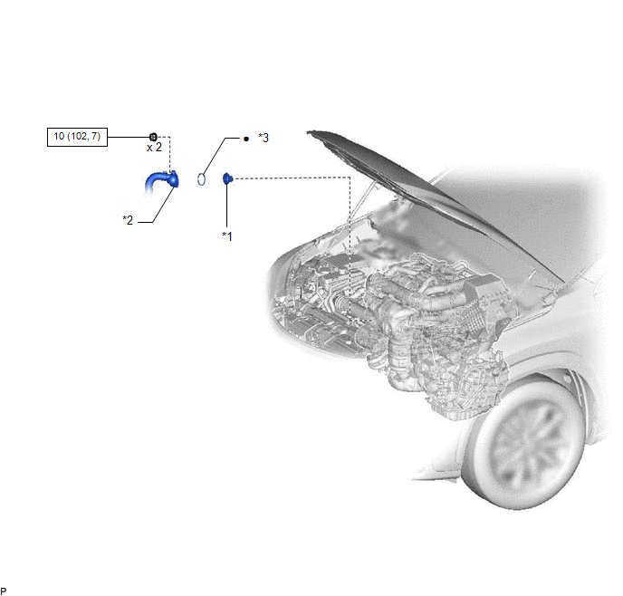
| *1 | THERMOSTAT | *2 | WATER INLET |
| *3 | GASKET | - | - |
.png) | N*m (kgf*cm, ft.*lbf): Specified torque | ● | Non-reusable part |
Removal
REMOVAL
PROCEDURE
1. DRAIN ENGINE COOLANT
Click here .gif)
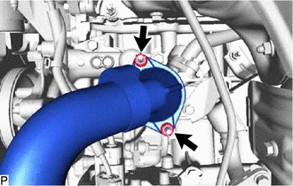
2. DISCONNECT WATER INLET
| (a) Remove the 2 nuts and disconnect the water inlet. |
|
3. REMOVE THERMOSTAT
| (a) Remove the thermostat. |
|
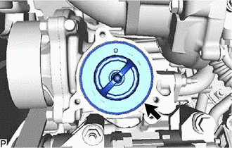
(b) Remove the gasket from the thermostat.
Inspection
INSPECTION
PROCEDURE
1. INSPECT THERMOSTAT
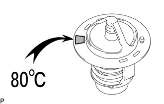
HINT:
The valve opening temperature is inscribed on the thermostat.
(a) Immerse the thermostat in water, and then gradually heat the water.
(b) Check that the valve of the thermostat opens at the specified temperature.
Standard valve opening temperature:
78 to 82°C (172 to 180°F)
If the valve does not open as specified, replace the thermostat.
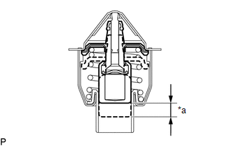
| (c) Check the valve lift. Standard valve lift: 10 mm (0.394 in.) or more at 93°C (199°F) If the valve lift is not as specified, replace the thermostat. |
|
(d) Check that the valve is fully closed when the thermostat is at a low temperature (below 75°C (167°F)).
If the valve is not fully closed, replace the thermostat.
Installation
INSTALLATION
PROCEDURE
1. INSTALL THERMOSTAT
(a) Install a new gasket to the thermostat.
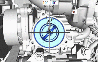
| (b) Install the thermostat with the jiggle valve facing upward. HINT: The jiggle valve may be set to within 10° on either side of the prescribed position. |
|
2. CONNECT WATER INLET
(a) Connect the water inlet with the 2 nuts.
Torque:
10 N·m {102 kgf·cm, 7 ft·lbf}
3. ADD ENGINE COOLANT
Click here .gif)
4. INSPECT FOR COOLANT LEAK
Click here
READ NEXT:
 Components
COMPONENTS ILLUSTRATION *1 ENGINE WATER PUMP ASSEMBLY *2 FAN AND GENERATOR V BELT *3 RADIATOR RESERVE TANK ASSEMBLY *4 V-RIBBED BELT TENSIONER ASSEMBLY *5 WATER BY-PASSS HOSE
On-vehicle Inspection
ON-VEHICLE INSPECTION CAUTION / NOTICE / HINT HINT:
Water Pump Construction Evaporation Port and Drain Plug: *1 Evaporation Port *2 Mechanical Seal *3 Fluid Catch Pocket *4 Drai
SEE MORE:
Installation
INSTALLATION CAUTION / NOTICE / HINT HINT: A bolt without a torque specification is shown in the standard bolt chart. Click here PROCEDURE 1. INSTALL FRONT BUMPER SIDE RETAINER LH Click here 2. INSTALL FRONT BUMPER SIDE RETAINER RH HINT: Use the same procedure described for the LH side. 3. INSTA
Rear Sensor Communication Malfunction (C1AED)
DESCRIPTION This DTC is stored when there is an open or short circuit in the communication line between the rear sensors and the ECU, or when there is a malfunction in a rear sensor. DTC No. Detection Item DTC Detection Condition Trouble Area C1AED Rear Sensor Communication Malfunctio
