Lexus NX: On-vehicle Inspection
ON-VEHICLE INSPECTION
CAUTION / NOTICE / HINT
HINT:
-
Water Pump Construction Evaporation Port and Drain Plug:
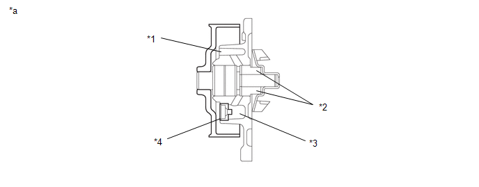
*1
Evaporation Port
*2
Mechanical Seal
*3
Fluid Catch Pocket
*4
Drain Plug
*a
Typical Water Pump Assembly
-
-
-
Water Pump Mechanical Seal
-
The water pump shaft is sealed by a mechanical type seal. Mechanical Seal Components:
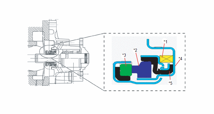
*1
Spring: Applies pressure to the seal ring to ensure the seal ring and mating ring are in constant contact.
*2
Seal Ring: Stationary sealing member in the water pump housing, held in place by the cartridge.
*3
Mating Ring: Rotates with the water pump shaft and provides sealing surface for the seal ring.
*4
Cartridge: Locates the seal ring and bellows in the water pump housing.
*5
Bellows: Seals the cartridge and the seal ring.
-
-
-
The water pump shaft is sealed by a mechanical type seal. Mechanical Seal Components:
-
Temporary Leaks
-
As the water pump assembly rotates, a small amount of engine coolant is discharged to cool and lubricate the sliding surface of the mechanical seal and evaporates.
(Water pump replacement is not necessary)
-
If debris becomes lodged between the mating ring and seal ring a small gap is formed. This allows coolant to bypass the mechanical seal, flow into the fluid catch pocket, and drain out of the weep hole. This condition is temporary and will no longer be present once the debris breaks up or works its way out of the seal.
(Water pump replacement is not necessary)
Examples (Dry Coolant Residue):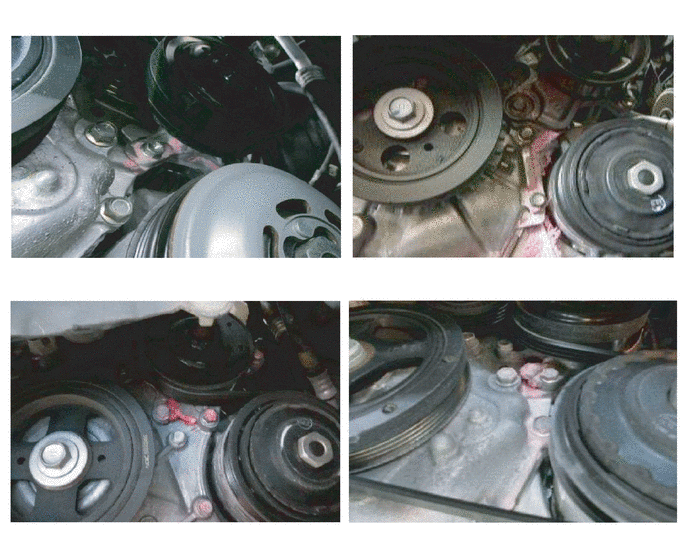 Examples (Wet Coolant Residue/Drips):
 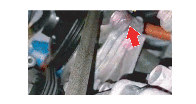 Debris in Mechanical Seal:
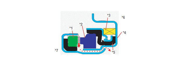
*1
Mating Ring
*2
Seal Ring: gap formed by debris
*3
Spring
*4
Cartridge
*5
Bellows
*6
Housing Side
*7
Impeller Side
-
-
-
As the water pump assembly rotates, a small amount of engine coolant is discharged to cool and lubricate the sliding surface of the mechanical seal and evaporates.
PROCEDURE
1. INSPECTION METHOD
(a) Perform a cooling system pressure check to confirm if there are leaks presentfrom areas of the cooling system other than the water pump.
Click here .gif)
(1) Are leaks preset in the cooling system other than from the water pump?
| Result | Proceed to |
|---|---|
| Yes | Continue leak diagnosis per the RM and correct any other cooling system leaks first before proceeding |
| No | Go to Step (b) |
(b) Is the coolant level below the "low" indicator on the reservoir?
| Result | Proceed to |
|---|---|
| Yes | Replace the water pump |
| No | Go to Step (c) |
(c) Does the water pump pulley/bearing have excessive free play or does not turn smoothly?
| Result | Proceed to |
|---|---|
| Yes | Replace the water pump |
| No | Go to Step (d) |
(d) A paper towel should be used to determine if a leak is active or was temporary due to debris that has now cleared.
Apply a dry paper towel to the coolant deposits around the water pump. If the paper towel remains dry the leak was temporary and the water pump does not need to be replaced.
If the paper towel becomes wet the leak is active and the water pump should be replaced.
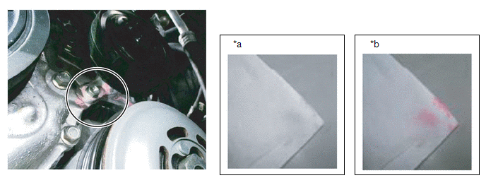
| *a | Dry Paper Towel: DO NOT Replace Water Pump | *b | Wet Paper Towel: Replace Water Pump |
Is the coolant residue wet on the paper towel?
| Result | Proceed to |
|---|---|
| Yes | Replace the water pump |
| No | No active leak is present, confirm coolant level in the reservoir is correct, clean any coolant residue from the engine and surrounding areas and return the vehicle to the customer. |
READ NEXT:
 Removal
REMOVAL PROCEDURE 1. DRAIN ENGINE COOLANT Click here 2. REMOVE FAN AND GENERATOR V BELT Click here 3. REMOVE RADIATOR RESERVE TANK ASSEMBLY (a) Slide the 2 clamps and disconnect the water by-pa
Installation
INSTALLATION PROCEDURE 1. INSTALL ENGINE WATER PUMP ASSEMBLY (a) Install a new gasket and the engine water pump assembly with the 5 bolts in the order shown in the illustration. Torque: 10 N·m {1
SEE MORE:
Data List / Active Test
DATA LIST / ACTIVE TEST DATA LIST Using the Techstream to read the Data List allows the values or states of switches, sensors, actuators and other items to be read without removing any parts. This non-intrusive inspection can be very useful because intermittent conditions or signals may be discovere
PTC Heater Circuit
DESCRIPTION The air conditioning amplifier assembly sends operation signals to the PTC heater relays when quick heater assembly operation conditions are met. Based on the signals from the air conditioning amplifier assembly, the PTC heater relays turn on, and power is supplied to the quick heater as
