Lexus NX: Removal
REMOVAL
CAUTION / NOTICE / HINT
NOTICE:
When replacing the windshield glass of a vehicle equipped with a forward recognition camera, make sure to use a Lexus genuine part. If a non-Lexus genuine part is used, the forward recognition camera may not be able to be installed due to a missing bracket. Also the dynamic radar cruise control system, front camera system, lane tracing assist system, road sign assist system, pre-collision system or automatic high beam system may not operate properly due to a difference in the transmissivity or black ceramic border.
PROCEDURE
1. REMOVE FRONT WIPER ARM HEAD CAP
Click here .gif)
2. REMOVE FRONT WIPER ARM LH
Click here
3. REMOVE FRONT WIPER ARM RH
Click here
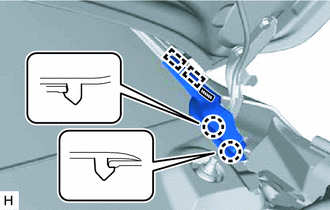
4. REMOVE FRONT FENDER TO COWL SIDE SEAL LH
(a) Detach the 2 claws.
.png) | Double-sided Tape |
(b) Detach the 2 guides.
(c) Remove the double-sided tape and front fender to cowl side seal LH.
5. REMOVE FRONT FENDER TO COWL SIDE SEAL RH
HINT:
Use the same procedure described for the LH side.
6. REMOVE COWL TOP VENTILATOR LOUVER SUB-ASSEMBLY
Click here
7. REMOVE WINDSHIELD OUTSIDE MOULDING LH
| (a) Put protective tape around the windshield outside moulding LH. |
|
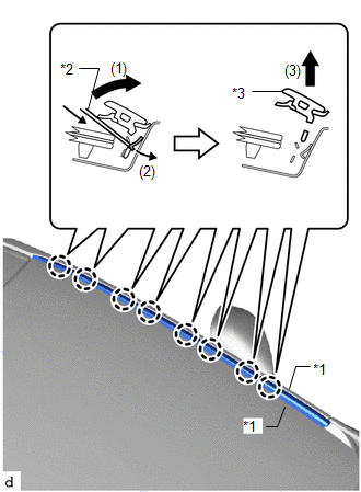
(b) Slide the upper end of the windshield outside moulding LH in the direction of the arrow (1) in the illustration to widen the gap between the windshield outside moulding LH and vehicle body.
(c) Insert moulding remover B between the windshield outside moulding LH and the top of the No. 1 windshield outside moulding clip.
(d) While pushing the claw on the upper portion of the No. 1 windshield outside moulding clip in the direction of the arrow (2) in the illustration, pull the moulding upward in the direction of the arrow (3) in the illustration and remove the upper portion of the windshield outside moulding LH.
NOTICE:
- Make sure that the No. 1 windshield outside moulding clip is not damaged when removing the windshield outside moulding LH.
- If the No. 1 windshield outside moulding clip is damaged, replace it with a new one.
8. REMOVE WINDSHIELD OUTSIDE MOULDING RH
HINT:
Use the same procedure described for the LH side.
9. REMOVE NO. 2 FORWARD RECOGNITION COVER
Click here
10. REMOVE NO. 1 FORWARD RECOGNITION COVER
Click here
11. REMOVE FORWARD RECOGNITION LATCH
Click here
12. REMOVE FORWARD RECOGNITION CAMERA
Click here
13. REMOVE FORWARD RECOGNITION WITH HEATER HOOD SUB-ASSEMBLY
Click here
14. REMOVE AIR CONDITIONING THERMISTOR ASSEMBLY (HUMIDITY SENSOR) (w/ Humidity Sensor)
Click here
15. REMOVE RAIN SENSOR (w/ Rain Sensor)
Click here
16. REMOVE INNER REAR VIEW MIRROR ASSEMBLY
Click here
17. REMOVE FRONT DOOR OPENING TRIM WEATHERSTRIP LH
Click here
18. REMOVE FRONT DOOR OPENING TRIM WEATHERSTRIP RH
HINT:
Use the same procedure described for the LH side.
19. REMOVE FRONT PILLAR GARNISH ASSEMBLY LH
Click here
20. REMOVE FRONT PILLAR GARNISH ASSEMBLY RH
HINT:
Use the same procedure described for the LH side.
21. REMOVE VISOR BRACKET COVER
Click here
22. REMOVE VISOR ASSEMBLY LH
Click here
23. REMOVE VISOR ASSEMBLY RH
HINT:
Use the same procedure described for the LH side.
24. REMOVE VISOR HOLDER
Click here
25. REMOVE MAP LIGHT ASSEMBLY
Click here
26. REMOVE ASSIST GRIP SUB-ASSEMBLY
Click here
27. REMOVE ROOF HEADLINING ASSEMBLY
HINT:
Remove a sufficient amount of the front portion of the roof headlining assembly so that windshield glass removal and installation procedures can be performed.
(a) Partially remove the roof headlining assembly.
(1) for Normal Roof:
Click here
(2) for Sliding Roof:
Click here
28. REMOVE WINDSHIELD GLASS
NOTICE:
- The windshield glass may fall while performing this procedure. Therefore, use suction cups to hold the windshield glass from the outside of the vehicle.
- Be careful not to damage the windshield glass when cutting as the No. 1 windshield glass stopper are installed to the windshield glass.
(a) Disconnect the each connector.
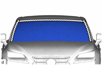
(b) Apply protective tape to the outer surface of the vehicle body to prevent scratches.
| | Protective Tape |
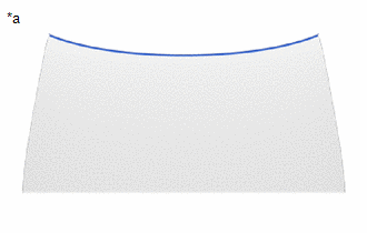
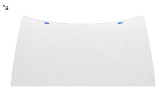
| (c) Place matchmarks over the glass and vehicle body at the locations indicated in the illustration. HINT: Matchmarks do not need to be placed if not reusing the glass. |
|
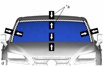
(d) Install the suction cups to the windshield glass.
| (e) From the interior, insert a piano wire between the vehicle body and glass as shown in the illustration. |
|
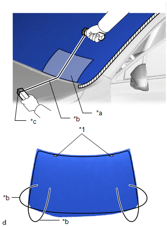
(f) Tie objects that can serve as handles (for example, wooden blocks) to both wire ends.
NOTICE:
- When separating the glass from the vehicle, be careful not to damage the vehicle paint or interior/exterior ornaments.
- To prevent the instrument panel from being scratched when removing the glass, place a plastic sheet between the piano wire and instrument panel.
(g) Cut through the adhesive by pulling the piano wire around the glass.
NOTICE:
Leave as much adhesive on the vehicle body as possible when cutting through the adhesive.
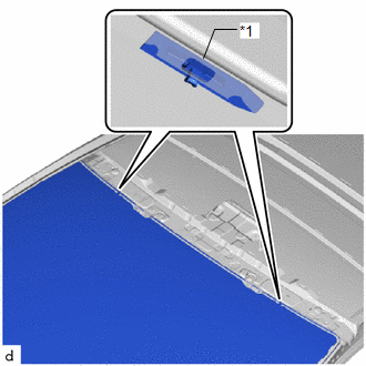
| (h) Disconnect the 2 No. 1 windshield glass stoppers. NOTICE:
HINT: Depending on the vehicle, either 1-piece or 2-piece type stoppers may be present. |
|
(i) Using suction cups, remove the windshield glass.
NOTICE:
- Be careful not to drop the windshield glass.
- Leave as much adhesive on the vehicle body as possible when removing the windshield glass.
29. REMOVE WINDSHIELD OUTSIDE MOULDING
| (a) When reusing the windshield glass: (1) Using a scraper, remove the windshield outside moulding. NOTICE:
|
|
30. REMOVE NO. 1 WINDSHIELD GLASS STOPPER
| (a) When reusing the windshield glass: (1) Using a scraper, remove the 2 No. 1 windshield glass stoppers. NOTICE:
|
|
31. REMOVE NO. 1 WINDSHIELD OUTSIDE MOULDING CLIP
HINT:
- Perform the following procedure if replacing the No. 1 windshield outside moulding clip.
- Use the same procedure for the other clips.
| (a) Put a 4 mm drill bit into a drill. Standard:
|
|
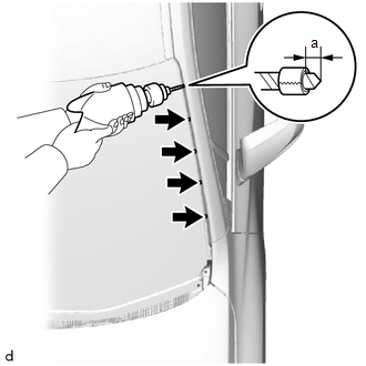
(b) Wind tape around the drill bit approximately 5 mm from the tip of the drill.
HINT:
Tape the 4 mm drill bit to prevent the drill bit from going too deep.
(c) Lightly press the drill against the No. 1 windshield outside moulding clip, grind the flanges of the No. 1 windshield outside moulding clip and remove the No. 1 windshield outside moulding clip.
NOTICE:
- Pressing the drill too firmly will cause the clip to turn and result in the clip not being drilled through.
- Do not pry the clip with the drill because this may cause damage to the installation holes of the clip or the drill bit.
- Be careful as the drilled clip may become hot.
(d) Remove the No. 1 windshield outside moulding clip.
READ NEXT:
 Installation
INSTALLATION CAUTION / NOTICE / HINT NOTICE:
When replacing the windshield glass of a vehicle equipped with a forward recognition camera, make sure to use a Lexus genuine part. If a non-Lexus genui
SEE MORE:
Components
COMPONENTS ILLUSTRATION *1 AIR CLEANER CAP SUB-ASSEMBLY *2 AIR CLEANER CASE SUB-ASSEMBLY *3 AIR CLEANER FILTER ELEMENT SUB-ASSEMBLY *4 ENGINE WIRE *5 FAN AND GENERATOR V BELT *6 GROUND WIRE *7 NO. 1 ENGINE COVER SUB-ASSEMBLY *8 RADIATOR RESERVE TANK ASSEMBLY
Removal
REMOVAL PROCEDURE 1. PRECAUTION NOTICE: After the power switch is turned off, there may be a waiting time before disconnecting the negative (-) auxiliary battery terminal. Click here 2. REMOVE NO. 3 DECK BOARD SUB-ASSEMBLY Click here 3. REMOVE REAR DECK FLOOR BOX Click here 4. REMOVE DECK FLOO
