.gif)
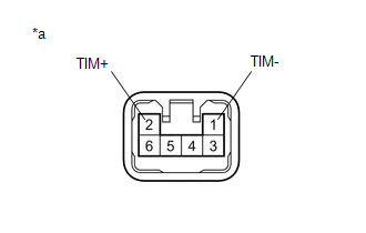
- 12 V battery positive (+) lead → Terminal 1 (TIM-)
- 12 V battery negative (-) lead → Terminal 2 (TIM+)
Lexus NX: Tilt Position Sensor or Tilt Motor Circuit Malfunction (B2610)
Lexus NX Service Manual / Steering / Steering Column / Power Tilt And Power Telescopic Steering Column System / Tilt Position Sensor or Tilt Motor Circuit Malfunction (B2610)
DESCRIPTION
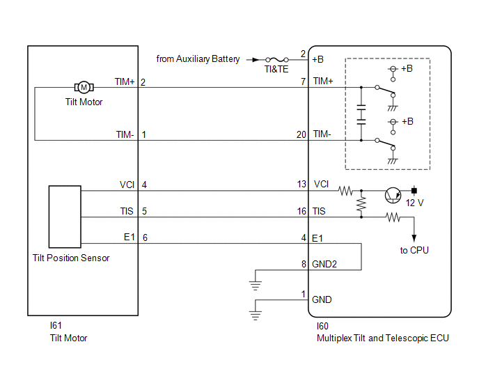
The tilt motor is operated by the power source voltage supplied from the multiplex tilt and telescopic ECU and tilts the steering column up and down. The tilt position sensor (Hall IC) in the tilt motor detects the tilt angle of the steering column and sends a signal to the multiplex tilt and telescopic ECU based on that angle.
| DTC No. | Detection Item | DTC Detection Condition | Trouble Area |
|---|---|---|---|
| B2610 | Tilt Position Sensor or Tilt Motor Circuit Malfunction | Tilt operation stops within the operation range while operating. |
|
WIRING DIAGRAM
CAUTION / NOTICE / HINT
NOTICE:
-
If the electric power steering column sub-assembly is replaced, perform actuator angle neutral point calibration.
Click here
.gif)
- Inspect the fuses for circuits related to this system before performing the following inspection procedure.
PROCEDURE
| 1. | PERFORM ACTIVE TEST USING TECHSTREAM (TILT OPERATION) |
(a) Turn the power switch off.
(b) Connect the Techstream to the DLC3.
(c) Turn the power switch on (IG).
(d) Turn the Techstream on.
(e) Check that the steering wheel tilts up and down.
(f) Enter the following menus: Body Electrical / Tilt & Telescopic / Active Test.
Body Electrical > Tilt&Telescopic > Active Test| Tester Display | Measurement Item | Control Range | Diagnostic Note |
|---|---|---|---|
| Tilt Operation | Tilt operation | Up/Down | - |
| Tester Display |
|---|
| Tilt Operation |
OK:
The steering wheel tilts up and down.
| NG | .gif) | GO TO STEP 6 |
|
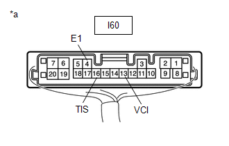
| 2. | CHECK HARNESS AND CONNECTOR (MULTIPLEX TILT AND TELESCOPIC ECU - TILT POSITION SENSOR) |
(a) Disconnect the I60 multiplex tilt and telescopic ECU connector.
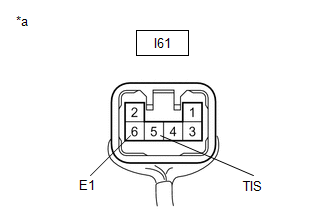
(b) Disconnect the I61 tilt motor connector.
(c) Measure the resistance according to the value(s) in the table below.
Standard Resistance:
| Tester Connection | Condition | Specified Condition |
|---|---|---|
| I60-13 (VCI) - I61-4 (VCI) | Always | Below 1 Ω |
| I60-16 (TIS) - I61-5 (TIS) | Always | Below 1 Ω |
| I60-4 (E1) -I61-6 (E1) | Always | Below 1 Ω |
| I60-13 (VCI) - Body ground | Always | 10 kΩ or higher |
| I60-16 (TIS) - Body ground | Always | 10 kΩ or higher |
| I60-4 (E1) - Body ground | Always | 10 kΩ or higher |
| NG | | REPAIR OR REPLACE HARNESS OR CONNECTOR |
|
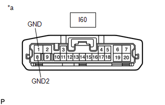
| 3. | CHECK HARNESS AND CONNECTOR (MULTIPLEX TILT AND TELESCOPIC ECU - BODY GROUND) |
| (a) Disconnect the I60 multiplex tilt and telescopic ECU connector. |
|
(b) Measure the resistance according to the value(s) in the table below.
Standard Resistance:
| Tester Connection | Condition | Specified Condition |
|---|---|---|
| I60-1 (GND) - Body ground | Always | Below 1 Ω |
| I60-8 (GND2) - Body ground | Always | Below 1 Ω |
| NG | | REPAIR OR REPLACE HARNESS OR CONNECTOR |
|
| 4. | CHECK MULTIPLEX TILT AND TELESCOPIC ECU (VCI, TIS TERMINAL VOLTAGE) |
| (a) Disconnect the I61 tilt motor connector. |
|
(b) Reconnect the I60 multiplex tilt and telescopic ECU connector.
(c) Measure the voltage according to the value(s) in the table below.
Standard Voltage:
| Tester Connection | Condition | Specified Condition |
|---|---|---|
| I60-13 (VCI) - I60-4 (E1) | Power switch on (IG) | 8 to 14 V |
| I60-16 (TIS) - I60-4 (E1) | Power switch on (IG) | 8 to 14 V |
| NG | | REPLACE MULTIPLEX TILT AND TELESCOPIC ECU |
|
| 5. | CHECK TILT POSITION SENSOR |
| (a) Reconnect the I60 multiplex tilt and telescopic ECU connector. |
|
(b) Reconnect the I61 tilt motor connector.
(c) Measure the voltage according to the value(s) in the table below.
Standard Voltage:
| Tester Connection | Condition | Specified Condition |
|---|---|---|
| I61-5 (TIS) - I61-6 (E1) | Steering wheel tilting up or tilting down | Pulse generation High: 8 to 14 V Low: Below 1 V |
| OK | | REPLACE MULTIPLEX TILT AND TELESCOPIC ECU |
| NG | | REPLACE ELECTRIC POWER STEERING COLUMN SUB-ASSEMBLY |
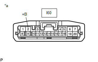
| 6. | CHECK HARNESS AND CONNECTOR (MULTIPLEX TILT AND TELESCOPIC ECU - AUXILIARY BATTERY) |
| (a) Disconnect the I60 multiplex tilt and telescopic ECU connector. |
|
(b) Measure the voltage according to the value(s) in the table below.
Standard Voltage:
| Tester Connection | Condition | Specified Condition |
|---|---|---|
| I60-2 (+B) - Body ground | Always | 11 to 14 V |
| NG | | REPAIR OR REPLACE HARNESS OR CONNECTOR |
|
| 7. | CHECK HARNESS AND CONNECTOR (MULTIPLEX TILT AND TELESCOPIC ECU - BODY GROUND) |
| (a) Disconnect the I60 multiplex tilt and telescopic ECU connector. |
|
(b) Measure the resistance according to the value(s) in the table below.
Standard Resistance:
| Tester Connection | Condition | Specified Condition |
|---|---|---|
| I60-1 (GND) - Body ground | Always | Below 1 Ω |
| I60-8 (GND2) - Body ground | Always | Below 1 Ω |
| NG | | REPAIR OR REPLACE HARNESS OR CONNECTOR |
|
| 8. | CHECK HARNESS AND CONNECTOR (MULTIPLEX TILT AND TELESCOPIC ECU - TILT MOTOR) |
(a) Disconnect the I60 multiplex tilt and telescopic ECU connector.
(b) Disconnect the I61 tilt motor connector.
(c) Measure the resistance according to the value(s) in the table below.
Standard Resistance:
| Tester Connection | Condition | Specified Condition |
|---|---|---|
| I60-7 (TIM+) - I61-2 (TIM+) | Always | Below 1 Ω |
| I60-20 (TIM-) - I61-1 (TIM-) | Always | Below 1 Ω |
| I60-7 (TIM+) - Body ground | Always | 10 kΩ or higher |
| I60-20 (TIM-) - Body ground | Always | 10 kΩ or higher |
| NG | | REPAIR OR REPLACE HARNESS OR CONNECTOR |
|
| 9. | CHECK TILT MOTOR |
| (a) Apply 12 V battery voltage to the tilt motor connector. Then check the steering wheel tilt operation. OK:
|
|
| OK | | REPLACE MULTIPLEX TILT AND TELESCOPIC ECU |
| NG | | REPLACE ELECTRIC POWER STEERING COLUMN SUB-ASSEMBLY |
READ NEXT:
 Telescopic Position Sensor or Telescopic Motor Circuit Malfunction (B2611)
DESCRIPTION The telescopic motor is operated by the power source voltage supplied from the multiplex tilt and telescopic ECU and slides the steering column forward and backward. The telescopic positio
ECU Power Source Circuit Malfunction (B2620)
DESCRIPTION The ECU power source circuit supplies positive (+) voltage to the multiplex tilt and telescopic ECU. DTC No. Detection Item DTC Detection Condition Trouble Area B2620 ECU Po
Vehicles Speed Malfunction (B2624)
DESCRIPTION The multiplex tilt and telescopic ECU forms a network with the ECUs of other systems via CAN communication. Each ECU informs the other ECUs that it is connected to the network by sending a
SEE MORE:
Voice is not Recognized
PROCEDURE 1. CHECK CONDITION (a) While paying attention to the condition of the spoken voice command, perform a voice recognition operation. OK: Voice command is recognized normally. HINT:
When the voice command is recognized, the content of the voice command is displayed in the voice r
Short in P Squib (Dual Stage - 2nd Step) Circuit (B1815-B1818)
DESCRIPTION The front passenger side squib 2nd step circuit consists of the airbag ECU assembly and instrument panel passenger airbag. The circuit instructs the SRS to deploy when deployment conditions are met. These DTCs are stored when a malfunction is detected in the front passenger side squib 2n
© 2016-2026 Copyright www.lexunx.com
