Lexus NX: Tonneau Cover Assembly
Components
COMPONENTS
ILLUSTRATION
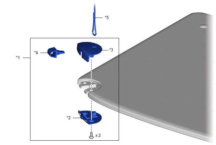
| *1 | NO. 1 TONNEAU COVER HOLDER CAP | *2 | TONNEAU COVER CAP PLATE |
| *3 | REAR TONNEAU COVER CAP | *4 | CUSHION |
| *5 | STRING | - | - |
Disassembly
DISASSEMBLY
CAUTION / NOTICE / HINT
HINT:
- Use the same procedure for the RH and LH sides.
- The procedure listed below is for the LH side.
PROCEDURE
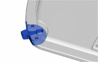
1. REMOVE NO. 1 TONNEAU COVER HOLDER CAP
(a) Remove the 2 screws and tonneau cover cap plate.
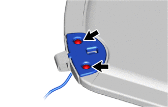
HINT:
If the string is caught on the hook of the tonneau cover plate cap, remove the string from the hook.
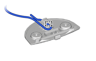
| (b) Pull out the string from the tonneau cover assembly. HINT: When replacing the No. 1 tonneau cover holder cap, reuse the string. |
|
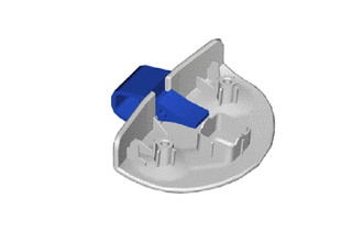
| (c) Remove the rear tonneau cover cap from the tonneau cover assembly. |
|
| (d) Remove the cushion. |
|
Reassembly
REASSEMBLY
CAUTION / NOTICE / HINT
HINT:
- Use the same procedure for the RH and LH sides.
- The procedure listed below is for the LH side.
PROCEDURE
1. INSTALL NO. 1 TONNEAU COVER HOLDER CAP
| (a) Install the cushion to the rear tonneau cover cap. |
|
.png)
| (b) Install the rear tonneau coer cap to the tonneau cover assembly. |
|
.png)
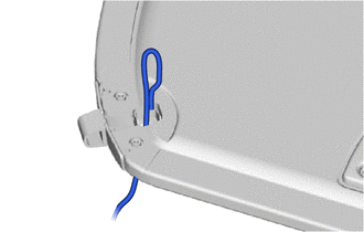
| (c) Pass the string on the tonneau cover assembly. |
|
.png)
| (d) Install the string to the hook of the tonneau cover cap plate. |
|
.png)
| (e) Install the tonneau cover cap plate with the 2 screws. |
|
.png)
READ NEXT:
 Precaution
PRECAUTION PRECAUTION FOR VEHICLE WITH AIRBAG (a) Some operations in this section may affect the airbag. Prior to performing the corresponding operations, read the SRS Precaution. Click here
Components
COMPONENTS ILLUSTRATION *1 DECK FLOOR BOX LH *2 NO. 3 DECK BOARD SUB-ASSEMBLY *3 REAR DECK FLOOR BOX *4 NEGATIVE AUXILIARY BATTERY TERMINAL N*m (kgf*cm, ft.*lbf): Specified
SEE MORE:
All Door Entry Lock/Unlock Functions do not Operate, but Wireless Functions Operate
DESCRIPTION When the wireless operation can be used to lock and unlock the doors, communication between the door control receiver and certification ECU (smart key ECU assembly) is normal. If the entry lock and unlock functions do not operate, the entry cancel function may be set through the customiz
Height Control Sensor Malfunction (B2416,B241A)
DESCRIPTION The headlight ECU sub-assembly LH supplies 5 V to the rear height control sensor LH, reads changes in the voltage that occur due to height sensor resistance changes according to the vehicle height, and performs auto leveling control. DTC No. Detection Item DTC Detection Condition
