Lexus NX: Components
COMPONENTS
ILLUSTRATION
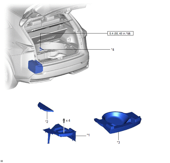
| *1 | DECK FLOOR BOX LH | *2 | NO. 3 DECK BOARD SUB-ASSEMBLY |
| *3 | REAR DECK FLOOR BOX | *4 | NEGATIVE AUXILIARY BATTERY TERMINAL |
.png) | N*m (kgf*cm, ft.*lbf): Specified torque | - | - |
ILLUSTRATION
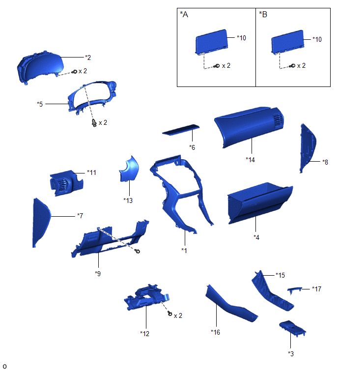
| *A | for 8 Inch Display | *B | for 10.3 Inch Display |
| *1 | CENTER INSTRUMENT CLUSTER FINISH PANEL ASSEMBLY | *2 | COMBINATION METER ASSEMBLY |
| *3 | CONSOLE ARMREST ASSEMBLY | *4 | GLOVE COMPARTMENT DOOR ASSEMBLY |
| *5 | INSTRUMENT CLUSTER FINISH PANEL SUB-ASSEMBLY | *6 | INSTRUMENT PANEL FINISH PLATE |
| *7 | INSTRUMENT SIDE PANEL LH | *8 | INSTRUMENT SIDE PANEL RH |
| *9 | LOWER NO. 1 INSTRUMENT PANEL FINISH PANEL | *10 | MULTI-DISPLAY ASSEMBLY WITH BRACKET |
| *11 | NO. 1 INSTRUMENT PANEL SAFETY PAD SUB-ASSEMBLY | *12 | NO. 1 INSTRUMENT PANEL UNDER COVER SUB-ASSEMBLY |
| *13 | NO. 1 SWITCH HOLE BASE | *14 | NO. 2 INSTRUMENT PANEL SAFETY PAD SUB-ASSEMBLY |
| *15 | UPPER NO. 1 CONSOLE PANEL GARNISH | *16 | UPPER NO. 2 CONSOLE PANEL GARNISH |
| *17 | UPPER REAR CONSOLE PANEL | - | - |
ILLUSTRATION
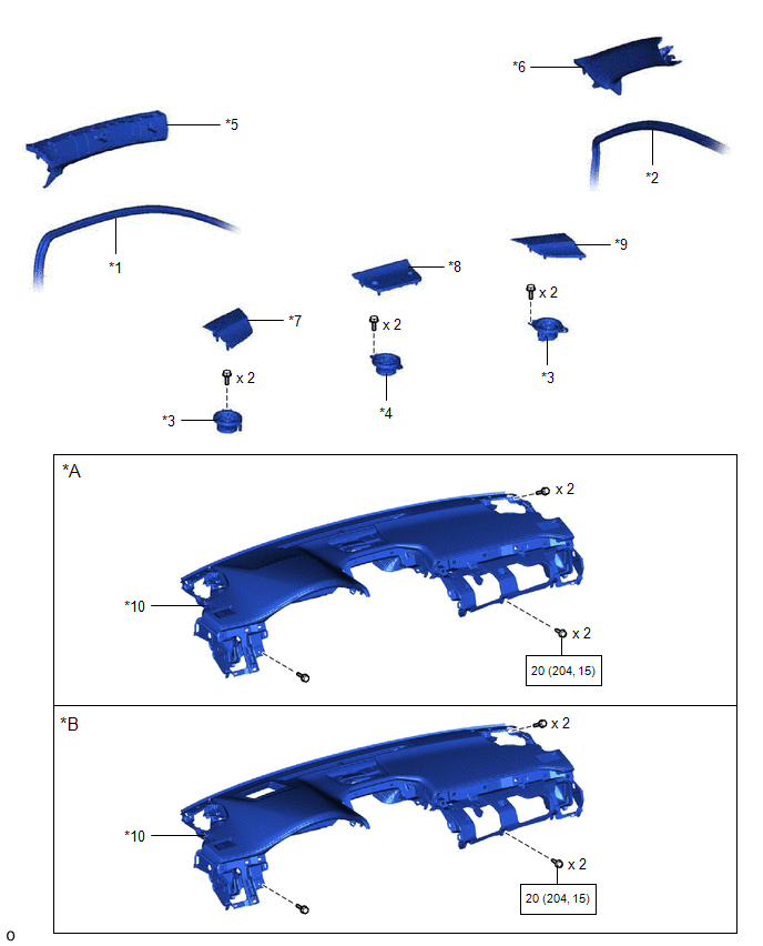
| *A | w/o Headup Display | *B | w/ Headup Display |
| *1 | FRONT DOOR OPENING TRIM WEATHERSTRIP LH | *2 | FRONT DOOR OPENING TRIM WEATHERSTRIP RH |
| *3 | FRONT NO. 2 SPEAKER ASSEMBLY | *4 | FRONT NO. 3 SPEAKER ASSEMBLY |
| *5 | FRONT PILLAR GARNISH ASSEMBLY LH | *6 | FRONT PILLAR GARNISH ASSEMBLY RH |
| *7 | NO. 1 INSTRUMENT PANEL SPEAKER PANEL SUB-ASSEMBLY | *8 | NO. 1 SPEAKER OPENING COVER ASSEMBLY |
| *9 | NO. 2 INSTRUMENT PANEL SPEAKER PANEL SUB-ASSEMBLY | *10 | UPPER INSTRUMENT PANEL SUB-ASSEMBLY |
| | N*m (kgf*cm, ft.*lbf): Specified torque | - | - |
ILLUSTRATION
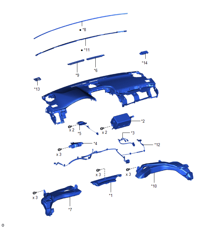
| *1 | DEFROSTER NOZZLE ASSEMBLY | *2 | INSTRUMENT PANEL PASSENGER WITHOUT DOOR AIRBAG ASSEMBLY |
| *3 | INSTRUMENT PANEL WIRE | *4 | METER HOOD SET BRACKET |
| *5 | NAVIGATION ANTENNA ASSEMBLY WITH BRACKET | *6 | NO. 1 DEFROSTER NOZZLE GARNISH |
| *7 | NO. 1 HEATER TO REGISTER DUCT SUB-ASSEMBLY | *8 | NO. 1 INSTRUMENT PANEL CUSHION |
| *9 | NO. 2 DEFROSTER NOZZLE GARNISH | *10 | NO. 2 HEATER TO REGISTER DUCT SUB-ASSEMBLY |
| *11 | NO. 2 INSTRUMENT PANEL CUSHION | *12 | NO. 2 INSTRUMENT PANEL WIRE |
| *13 | SIDE DEFROSTER NOZZLE LH | *14 | SIDE DEFROSTER NOZZLE RH |
| ● | Non-reusable part | - | - |
ILLUSTRATION
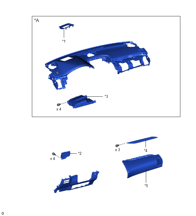
| *A | w/ Headup Display | - | - |
| *1 | INSTRUMENT CLUSTER FINISH PANEL ASSEMBLY | *2 | LOWER NO. 2 INSTRUMENT PANEL FINISH PANEL |
| *3 | METER MIRROR SUB-ASSEMBLY (HEADUP DISPLAY) | *4 | NO. 2 INSTRUMENT CLUSTER FINISH PANEL GARNISH |
| *5 | NO. 2 INSTRUMENT PANEL SAFETY PAD SUB-ASSEMBLY | - | - |
READ NEXT:
 Removal
REMOVAL PROCEDURE 1. TABLE OF BOLT, SCREW AND CLIP HINT: All bolts, screws, and clips relevant to installing and removing the instrument panel are shown along with their alphabet code in the table bel
Disassembly
DISASSEMBLY PROCEDURE 1. REMOVE NO. 1 HEATER TO REGISTER DUCT SUB-ASSEMBLY (a) Remove the 3 screws <A> or <B> and No. 1 heater to register duct sub-assembly. *a Screw <
Reassembly
REASSEMBLY PROCEDURE 1. INSTALL LOWER NO. 2 INSTRUMENT PANEL FINISH PANEL (a) Install the lower No. 2 instrument panel finish panel with the 4 screws. 2. INSTALL NO. 2 INSTRUMENT CLUSTE
SEE MORE:
Installation
INSTALLATION CAUTION / NOTICE / HINT HINT:
Use the same procedure for the RH and LH sides.
The procedures listed below are for the LH side.
PROCEDURE 1. INSTALL FRONT DOOR LOWER OUTSIDE MOULDING SUB-ASSEMBLY LH HINT: When installing the front door lower outside moulding sub-assembly LH, heat
Removal
REMOVAL CAUTION / NOTICE / HINT CAUTION: Wear protective gloves. Sharp areas on the parts may injure your hands. PROCEDURE 1. REMOVE TONNEAU COVER ASSEMBLY Click here 2. REMOVE DECK BOARD ASSEMBLY Click here 3. REMOVE BENCH TYPE REAR SEAT CUSHION ASSEMBLY (a) Lift the front end of the rear
