Lexus NX: Only Back Door cannot be Opened
DESCRIPTION
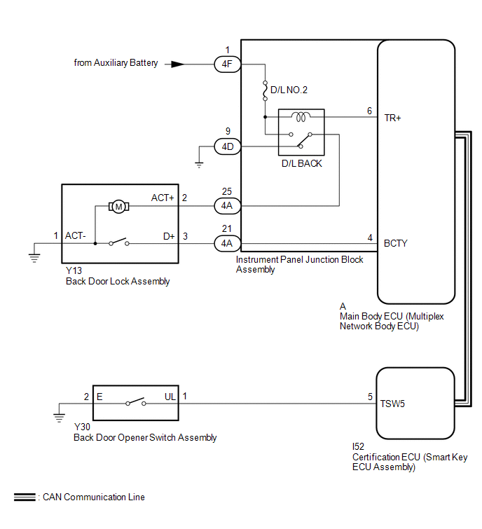
The main body ECU (multiplex network body ECU) receives signals from the back door opener switch assembly. Then, the main body ECU (multiplex network body ECU) activates the back door lock motor.
WIRING DIAGRAM
CAUTION / NOTICE / HINT
NOTICE:
- When using the Techstream with the vehicle power switch off, connect the Techstream to the DLC3 and turn a courtesy light switch on and off at intervals of 1.5 seconds or less until communication between the Techstream and the vehicle begins. Then select Model Code "KEY REGIST" under manual mode and enter the following menus: Body Electrical / Entry&Start(CAN). While using the Techstream, periodically turn a courtesy light switch on and off at intervals of 1.5 seconds or less to maintain communication between the Techstream and the vehicle.
- Inspect the fuses for circuits related to this system before performing the following procedure.
-
If the main body ECU (multiplex network body ECU) is replaced, refer to the Smart Access System with Push-button Start (for Entry Function).
Click here
.gif)
-
The power door lock control system uses the CAN communication system. Inspect the communication function by following How to Proceed with Troubleshooting. Troubleshoot the power door lock control system after confirming that the communication systems are functioning properly.
Click here
PROCEDURE
| 1. | PERFORM ACTIVE TEST USING TECHSTREAM (Trunk and Back-Door Open) |
(a) Connect the Techstream to the DLC3.
(b) Turn the power switch on (IG).
(c) Turn the Techstream on.
(d) Enter the following menus: Body Electrical / Main Body / Active Test.
(e) Perform the Active Test according to the display on the Techstream.
Body Electrical > Main Body > Active Test| Tester Display | Measurement Item | Control Range | Diagnostic Note |
|---|---|---|---|
| Trunk and Back-Door Open | Back door lock motor | OFF/ON | - |
| Tester Display |
|---|
| Trunk and Back-Door Open |
OK:
The back door lock assembly unlatches when ON is selected.
| OK | .gif) | GO TO SMART ACCESS SYSTEM WITH PUSH-BUTTON START (for Entry Function) |
|
.gif)
| 2. | INSPECT BACK DOOR LOCK ASSEMBLY |
(a) Remove the back door lock assembly.
Click here
(b) Inspect the back door lock assembly.
Click here
| NG | | REPLACE BACK DOOR LOCK ASSEMBLY |
|
| 3. | CHECK HARNESS AND CONNECTOR (BACK DOOR LOCK ASSEMBLY - INSTRUMENT PANEL JUNCTION BLOCK ASSEMBLY AND BODY GROUND) |
(a) Disconnect the Y13 back door lock assembly connector.
(b) Disconnect the 4A instrument panel junction block assembly connector.
(c) Measure the resistance according to the value(s) in the table below.
Standard Resistance:
| Tester Connection | Condition | Specified Condition |
|---|---|---|
| Y13-1 (ACT+) - 4A-25 | Always | Below 1 Ω |
| Y13-3 (D+) - 4A-21 | Always | Below 1 Ω |
| Y13-2 (ACT-) - Body ground | Always | Below 1 Ω |
| Y13-1 (ACT+) or 4A-25 - Body ground | Always | 10 kΩ or higher |
| Y13-3 (D+) or 4A-21 - Body ground | Always | 10 kΩ or higher |
| NG | | REPAIR OR REPLACE HARNESS OR CONNECTOR |
|
| 4. | INSPECT INSTRUMENT PANEL JUNCTION BLOCK ASSEMBLY |
(a) Remove the instrument panel junction block assembly.
Click here
(b) Remove the main body ECU (multiplex network body ECU) from the instrument panel junction block assembly.
(c) Measure the resistance according to the value(s) in the table below.
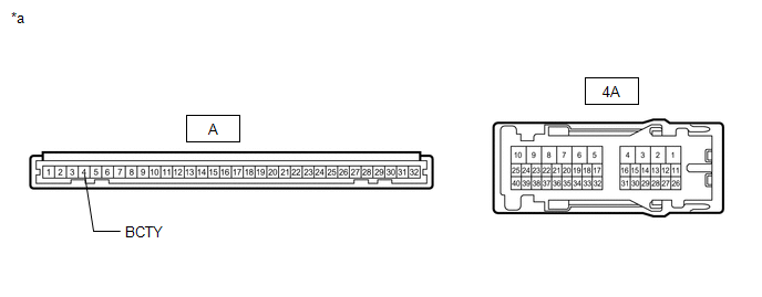
| *a | Component without harness connected (Instrument Panel Junction Block Assembly) | - | - |
Standard Resistance:
| Tester Connection | Condition | Specified Condition |
|---|---|---|
| A-4 (BCTY) - 4A-21 | Always | Below 1 Ω |
| NG | | REPLACE INSTRUMENT PANEL JUNCTION BLOCK ASSEMBLY |
|
| 5. | CHECK INSTRUMENT PANEL JUNCTION BLOCK ASSEMBLY (D/L BACK RELAY) |
(a) Disconnect the instrument panel junction block assembly connector.
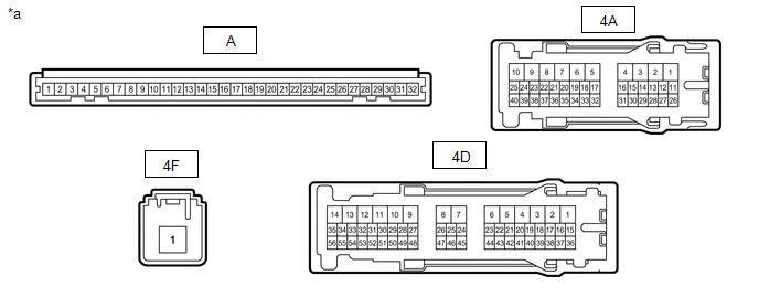
| *a | Front view of wire harness connector (to Instrument Panel Junction Block Assembly) | - | - |
(b) Measure the resistance according to the value(s) in the table below.
Standard Resistance:
| Tester Connection | Condition | Specified Condition |
|---|---|---|
| 4A-25 - 4D-9 | Auxiliary battery voltage applied to terminals 4F-1 and A-6 | 10 kΩ or higher |
| 4A-25 - 4D-9 | Auxiliary battery voltage not applied to terminals 4F-1 and A-6 | Below 1 Ω |
(c) Measure the voltage according to the value(s) in the table below.
Standard Voltage:
| Tester Connection | Condition | Specified Condition |
|---|---|---|
| 4A-25 - Auxiliary battery negative (-) terminal | Auxiliary battery voltage applied to terminals 4F-1 and A-6 | 11 to 14 V |
| OK | | REPLACE MAIN BODY ECU (MULTIPLEX NETWORK BODY ECU) |
| NG | | REPLACE INSTRUMENT PANEL JUNCTION BLOCK ASSEMBLY |
READ NEXT:
 Components
COMPONENTS ILLUSTRATION *1 DECK FLOOR BOX LH *2 NO. 3 DECK BOARD SUB-ASSEMBLY *3 REAR DECK FLOOR BOX *4 NEGATIVE AUXILIARY BATTERY TERMINAL N*m (kgf*cm, ft.*lbf): Specified
Removal
REMOVAL CAUTION / NOTICE / HINT HINT:
Use the same procedure for the RH and LH sides.
The procedure listed below is for the LH side.
PROCEDURE 1. PRECAUTION NOTICE: After turning the power swi
SEE MORE:
Problem Symptoms Table
PROBLEM SYMPTOMS TABLE NOTICE: If the auxiliary battery voltage becomes low, windshield deicer operation is canceled to prioritize supplying power to the power steering system. for Power Tilt and Power Telescopic Steering Column: Click here for Manual Tilt and Manual Telescopic Steering Column: Cl
Precaution
PRECAUTION NOTICE: When disassembling the rear combination light assembly, use static electricity countermeasures SST (desktop antistatic mat set) and observe all precautions to prevent damage to the system by electrostatic discharge (ESD). STATIC ELECTRICITY COUNTERMEASURES SST SST:Desktop antistat
