- Power switch on (IG), shift lever is P → other than P
- Power switch on (IG), stop light switch assembly on → off
- Power switch on (IG), parking brake switch assembly on → off
Lexus NX: Park / Neutral Position Switch Circuit
Lexus NX Service Manual / Vehicle Interior / Seat / Rear Power Seat Control System / Park / Neutral Position Switch Circuit
DESCRIPTION
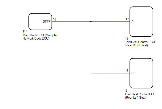
The fold seat control ECU receives switch operation signals, back door open/close signal*1, rear door open/close signal*2 and driving condition signal (shift position, stop light switch assembly, parking brake switch assembly signals) from the main body ECU (multiplex network body ECU). Then, the fold seat control ECU actives the rear seat according these signals.
- *1: Using No. 2 fold seat switch assembly
- *2: Using rear power seat switch
WIRING DIAGRAM
CAUTION / NOTICE / HINT
NOTICE:
If the main body ECU (multiplex network body ECU) is replaced, refer to the Smart Access System with Push-button Start (for Entry Function).
Click here .gif)
PROCEDURE
| 1. | CHECK FOLD SEAT CONTROL ECU (PARK/NEUTRAL POSITION SWITCH SIGNAL) |
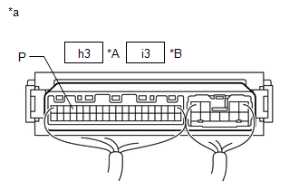
| *A | Rear Right Seat |
| *B | Rear Left Seat |
| *a | Component with harness connected (Fold Seat Control ECU) |
(a) Remove the fold seat control ECU with its connectors still connected.
Click here
(b) Measure the voltage according to the value(s) in the table below.
Standard Voltage:
Rear Right Seat| Tester Connection | Condition | Specified Condition |
|---|---|---|
| h3-17 (P) - Body ground | | 11 to 14 V → Below 1 V |
| Power switch off | 11 to 14 V |
| Tester Connection | Condition | Specified Condition |
|---|---|---|
| i3-17 (P) - Body ground |
| 11 to 14 V → Below 1 V |
| Power switch off | 11 to 14 V |
| OK | .gif) | PROCEED TO NEXT SUSPECTED AREA SHOWN IN PROBLEM SYMPTOMS TABLE |
|
.gif)
| 2. | CHECK HARNESS AND CONNECTOR (FOLD SEAT CONTROL ECU - MAIN BODY ECU [MULTIPLEX NETWORK BODY ECU]) |
(a) Disconnect the h3*1 or i3*2 fold seat control ECU connectors.
- *1: Rear Right Seat
- *2: Rear Left Seat
(b) Disconnect the I47 main body ECU (multiplex network body ECU) connector.
(c) Measure the resistance according to the value(s) in the table below.
Standard Resistance:
Rear Right Seat
| Tester Connection | Condition | Specified Condition |
|---|---|---|
| h3-17 (P) - I47-16 (SFTP) | Always | Below 1 Ω |
| h3-17 (P) or I47-16 (SFTP) - Body ground | Always | 10 kΩ or higher |
Rear Left Seat
| Tester Connection | Condition | Specified Condition |
|---|---|---|
| i3-17 (P) - I47-16 (SFTP) | Always | Below 1 Ω |
| i3-17 (P) or I47-16 (SFTP) - Body ground | Always | 10 kΩ or higher |
| NG | | REPAIR OR REPLACE HARNESS OR CONNECTOR |
|
| 3. | CHECK FOLD SEAT CONTROL ECU |
(a) Replace the fold seat control ECU with a new or normally functioning one.
Click here
(b) Check the rear power seat control system.
Click here
OK:
The rear power seat control system is operated normally.
| OK | | END (FOLD SEAT CONTROL ECU WAS DEFECTIVE) |
| NG | | REPLACE MAIN BODY ECU (MULTIPLEX NETWORK BODY ECU) |
READ NEXT:
 Rear Door Courtesy Switch Circuit
DESCRIPTION The fold seat control ECU receives the switch operation signal, driving condition signal and rear door open/close signal. Then the fold seat control ECU actives the rear seat according to
Back Door Courtesy Switch Circuit
DESCRIPTION The fold seat control ECU receives the switch operation signal, driving condition signal and back door open/close signal from the back door lock assembly. The fold seat control ECU actives
Fold Seat Switch Circuit
DESCRIPTION When the fold seat switch is operated, a switch operation signal is sent to the fold seat control ECU. The ECU receives switch operation signals from each switch and activates the reclinin
SEE MORE:
Data List / Active Test
DATA LIST / ACTIVE TEST NOTICE: In the table below, the values listed under "Normal Condition" are reference values. Do not depend solely on these reference values when deciding whether a part is faulty or not. DATA LIST HINT:
Using the Techstream to read the Data List allows the values or states
Diagnosis System
DIAGNOSIS SYSTEM DESCRIPTION (a) Diagnostic Trouble Codes (DTCs) for the LEXUS ENFORM system can be read from the Data Link Connector 3 (DLC3) of the vehicle. When the system seems to be malfunctioning, use the Techstream to check for malfunctions and to repair it. CHECK DLC3 (a) Check the DLC3. Cli
© 2016-2026 Copyright www.lexunx.com
