- Power Supply Condition
- IG Relay Monitor (Inside)
- IG Relay Monitor (Outside)
- IG Circuit
Lexus NX: Power Source Mode does not Change to ON (IG)
Lexus NX Service Manual / Vehicle Interior / Theft Deterrent / Keyless Entry / Smart Access System With Push-button Start (for Start Function) / Power Source Mode does not Change to ON (IG)
DESCRIPTION
If the power switch is pressed with the electrical key transmitter sub-assembly in the cabin, the certification ECU (smart key ECU assembly) receives a signal and changes the power source mode.
Related Data List and Active Test Items| Problem Symptom | Data List and Active Test |
|---|---|
| Power source mode does not change to on (IG) but does change to on (ACC) | Power Source Control |
WIRING DIAGRAM
Click here .gif)
CAUTION / NOTICE / HINT
NOTICE:
- When using the Techstream with the power switch off, connect the Techstream to the DLC3 and turn a courtesy light switch on and off at intervals of 1.5 seconds or less until communication between the Techstream and the vehicle begins. Then select the vehicle type under manual mode and enter the following menus: Body Electrical / Smart Access. While using the Techstream, periodically turn a courtesy light switch on and off at intervals of 1.5 seconds or less to maintain communication between the Techstream and the vehicle.
-
The smart access system with push-button start (for Start Function) uses the LIN communication system and CAN communication system. Inspect the communication function by following How to Proceed with Troubleshooting. Troubleshoot the smart access system with push-button start (for Start Function) after confirming that the communication systems are functioning properly.
Click here
- Make sure that no DTCs are output. If any DTCs are output, proceed to Diagnostic Trouble Code Chart.
-
If the smart access system with push-button start (for Start Function) has been canceled, enable the system before performing troubleshooting.
Click here
- Inspect the fuses of circuits related to this system before performing the following procedure.
-
Before replacing the certification ECU (smart key ECU assembly), refer to smart access system with push-button start (for Start Function) Precaution.
Click here
- After completing repairs, confirm that the problem does not recur.
HINT:
When the cable is disconnected and reconnected to the negative (-) auxiliary battery terminal, the power source mode returns to the state it was in before the cable was disconnected.
PROCEDURE
| 1. | CHECK FOR DTC |
(a) Using the Techstream, check for DTCs.
Body Electrical > Power Source Control > Trouble Codes Body Electrical > Smart Access > Trouble Codes| Result | Proceed to |
|---|---|
| DTCs are not output | A |
| Smart access system with push-button start (for Start Function) DTCs are output | B |
| B | .gif) | GO TO DIAGNOSTIC TROUBLE CODE CHART |
|
.gif)
| 2. | CHECK HARNESS AND CONNECTOR (CERTIFICATION ECU (SMART KEY ECU ASSEMBLY) - INSTRUMENT PANEL JUNCTION BLOCK ASSEMBLY) |
(a) Disconnect the I51 certification ECU (smart key ECU assembly) connector.
(b) Disconnect the 4C and 4D instrument panel junction block assembly connectors.
(c) Measure the resistance according to the value(s) in the table below.
Standard Resistance:
| Tester Connection | Condition | Specified Condition |
|---|---|---|
| I51-3 (IG1D) - 4C-44 | Always | Below 1 Ω |
| 4D-9 - Body ground | Always | Below 1 Ω |
| I51-3 (IG1D) or 4C-44 - Body ground | Always | 10 kΩ or higher |
| NG | | REPAIR OR REPLACE HARNESS OR CONNECTOR |
|
| 3. | CHECK HARNESS AND CONNECTOR (INSTRUMENT PANEL JUNCTION BLOCK ASSEMBLY - IG1 RELAY) |
(a) Remove the IG1 relay.
(b) Disconnect the 4B instrument panel junction block assembly connector.
(c) Measure the resistance according to the value(s) in the table below.
Standard Resistance:
| Tester Connection | Condition | Specified Condition |
|---|---|---|
| 4B-46 - 1 (IG1 relay) | Always | Below 1 Ω |
| 2 (IG1 relay) - Body ground | Always | Below 1 Ω |
| 4B-46 or 1 (IG1 relay) - Body ground | Always | 10 kΩ or higher |
| NG | | REPAIR OR REPLACE HARNESS OR CONNECTOR |
|
| 4. | CHECK HARNESS AND CONNECTOR (INSTRUMENT PANEL JUNCTION BLOCK ASSEMBLY - IG2-MAIN RELAY) |
(a) Disconnect the 4B instrument panel junction block assembly connector.
(b) Remove the IG2-MAIN relay.
(c) Measure the resistance according to the value(s) in the table below.
Standard Resistance:
| Tester Connection | Condition | Specified Condition |
|---|---|---|
| 4B-55 - 1 (IG2-MAIN relay) | Always | Below 1 Ω |
| 2 (IG2-MAIN relay) - Body ground | Always | Below 1 Ω |
| 4B-55 or 1 (IG2-MAIN relay) - Body ground | Always | 10 kΩ or higher |
| NG | | REPAIR OR REPLACE HARNESS OR CONNECTOR |
|
| 5. | CHECK INSTRUMENT PANEL JUNCTION BLOCK ASSEMBLY (IG1 NO. 1, IG1 NO. 2, IG1 NO. 3 RELAY) |
(a) Remove the instrument panel junction block assembly.
Click here
(b) Measure the resistance according to the value(s) in the table below.
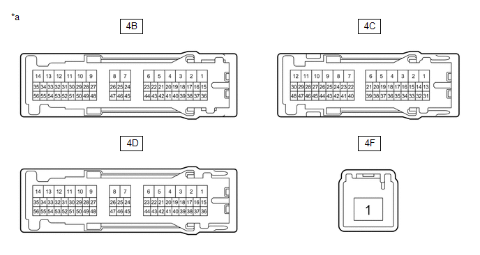
| *a | Component without harness connected (Instrument Panel Junction Block Assembly) | - | - |
Standard Resistance:
| Tester Connection | Condition | Specified Condition |
|---|---|---|
| 4C-44 - 4D-9 | 20°C (68°F) | 87.32 to 127.14 Ω |
| 4F-1 - 4C-25 | Auxiliary battery voltage applied to terminals 4C-44 and 4D-9 | Below 1 Ω |
| Auxiliary battery voltage not applied to terminals 4C-44 and 4D-9 | 10 kΩ or higher | |
| 4F-1 - 4C-45 | Auxiliary battery voltage applied to terminals 4C-44 and 4D-9 | Below 1 Ω |
| Auxiliary battery voltage not applied to terminals 4C-44 and 4D-9 | 10 kΩ or higher | |
| 4F-1 - 4B-50 | Auxiliary battery voltage applied to terminals 4C-44 and 4D-9 | Below 1 Ω |
| Auxiliary battery voltage not applied to terminals 4C-44 and 4D-9 | 10 kΩ or higher |
| NG | | REPLACE INSTRUMENT PANEL JUNCTION BLOCK ASSEMBLY |
|
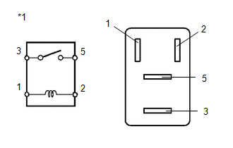
| 6. | INSPECT IG1 RELAY |
(a) Remove the IG1 relay.
| (b) Measure the resistance according to the value(s) in the table below. Standard Resistance:
|
|
| NG | | REPLACE IG1 RELAY |
|
| 7. | INSPECT IG2-MAIN RELAY |
(a) Remove the IG2-MAIN relay.
| (b) Measure the resistance according to the value(s) in the table below. Standard Resistance:
|
|
| NG | | REPLACE IG1 MAIN RELAY |
|
| 8. | CHECK CERTIFICATION ECU (SMART KEY ECU ASSEMBLY) |
(a) Reconnect the I51 certification ECU (smart key ECU assembly) connector.
(b) Install the instrument panel junction block assembly.
Click here
(c) Install the IG1 relay.
(d) Install the IG2-MAIN relay.
| (e) Measure the voltage according to the value(s) in the table below. Standard Voltage:
|
|
.png)
| OK | | USE SIMULATION METHOD TO CHECK |
| NG | | REPLACE CERTIFICATION ECU (SMART KEY ECU ASSEMBLY) |
READ NEXT:
 Power Source Mode does not Change to ON (ACC)
DESCRIPTION If the power switch is pressed with the electrical key transmitter sub-assembly in the cabin, the certification ECU (smart key ECU assembly) receives a signal and changes the power source
Power Source Mode does not Change to ON (READY)
DESCRIPTION When the electrical key transmitter sub-assembly is in the cabin and the power switch is pressed, the certification ECU (smart key ECU assembly) receives a signal and changes the power sou
SEE MORE:
How To Proceed With Troubleshooting
CAUTION / NOTICE / HINT HINT:
Use these procedures to troubleshoot the power steering system.
*: Use the Techstream.
PROCEDURE 1. VEHICLE BROUGHT TO WORKSHOP
NEXT 2. INSPECT AUXILIARY BATTERY VOLTAGE (a) Measure the voltage of the auxiliary battery. Standar
Front Airbag Sensor Lost Communication (LH) (B1617,B1618)
DESCRIPTION The front airbag sensor LH circuit consists of the airbag ECU assembly and front airbag sensor LH. The front airbag sensor LH detects impacts to the vehicle and sends signals to the airbag ECU assembly to determine if the airbag should be deployed. DTC B1617 or B1618 is stored when a mal
© 2016-2026 Copyright www.lexunx.com
