Lexus NX: A/C Inverter Start-up Signal System Malfunction (B1473)
DESCRIPTION
The inverter activation signal is sent to the compressor with motor assembly from the hybrid vehicle control ECU. Compressor control is stopped and this DTC is stored if there is an open or short in the signal circuit.
| DTC No. | Detection Item | DTC Detection Condition | Trouble Area | Memory | Note |
|---|---|---|---|---|---|
| B1473 | A/C Inverter Start-up Signal System Malfunction | Open or short in A/C inverter start-up signal system |
| - | - |
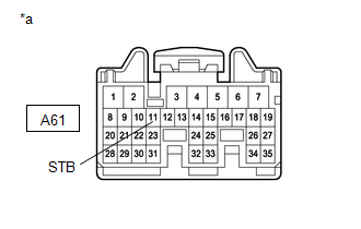
WIRING DIAGRAM
.png)
CAUTION / NOTICE / HINT
CAUTION:
- Wear insulated gloves and pull out the service plug grip before inspection as procedures may require disconnecting high-voltage connectors. Carry the removed service plug in your pocket to prevent other technicians from accidentally reconnecting it while you are servicing the vehicle.
- Do not touch the high-voltage connectors or terminals for 10 minutes after the service plug grip is removed.
NOTICE:
-
After the power switch is turned off, there may be a waiting time before disconnecting the negative (-) auxiliary battery terminal.
Click here
.gif)
-
When disconnecting and reconnecting the auxiliary battery terminal
Click here
HINT:
When disconnecting and reconnecting the auxiliary battery, there is an automatic learning function that completes learning when the respective system is used.
Click here
- The hybrid control system and air conditioning system output DTCs separately. Perform troubleshooting for the hybrid control system first if DTCs from these systems are output simultaneously.
PROCEDURE
| 1. | CHECK CAN COMMUNICATION SYSTEM |
(a) Using the Techstream, check if the CAN communication system is functioning normally.
Click here
| Result | Proceed to |
|---|---|
| CAN communication system DTCs are not output | A |
| CAN communication system DTCs are output | B |
| B | .gif) | GO TO CAN COMMUNICATION SYSTEM |
|
.gif)
| 2. | CHECK FOR DTC |
(a) Check if air conditioning system and hybrid control system DTCs are output.
Click here
Click here
| Result | Proceed to |
|---|---|
| Only DTC B1473 is output | A |
| DTCs B1473 and P3108 are output simultaneously (B1498 is not output) | |
| DTCs B1473 and B1498 are output simultaneously (P3108 is not output) | B |
| DTCs B1473, B1498 and P3108 are output simultaneously | |
| DTCs other than P3108 are output for hybrid control system | C |
| B | | GO TO DTC B1498 |
| C | | GO TO HYBRID CONTROL SYSTEM |
|
| 3. | CHECK HARNESS AND CONNECTOR (HYBRID VEHICLE CONTROL ECU - COMPRESSOR WITH MOTOR ASSEMBLY) |
CAUTION:
Do not disconnect the connector on the high-voltage side.
(a) Disconnect the A61 hybrid vehicle control ECU connector.
(b) Disconnect the C43 compressor with motor assembly connector.
NOTICE:
Do not allow any foreign matter or water to enter the compressor with motor assembly.
(c) Measure the resistance according to the value(s) in the table below.
Standard Resistance:
| Tester Connection | Condition | Specified Condition |
|---|---|---|
| A61-11 (STB) - C43-4 (STBI) | Always | Below 1 Ω |
| A61-11 (STB) or C43-4 (STBI) - Body ground | Always | 10 kΩ or higher |
| NG | | REPAIR OR REPLACE HARNESS OR CONNECTOR |
|
| 4. | INSPECT COMPRESSOR WITH MOTOR ASSEMBLY |
(a) Disconnect the hybrid vehicle control ECU connector.
| (b) Measure the voltage according to the value(s) in the table below. Standard Voltage:
|
|
| OK | | REPLACE HYBRID VEHICLE CONTROL ECU |
| NG | | REPLACE COMPRESSOR WITH MOTOR ASSEMBLY |
READ NEXT:
 A/C Inverter Malfunction (B1474)
DESCRIPTION DTC No. Detection Item DTC Detection Condition Trouble Area Memory Note B1474 A/C Inverter Malfunction A/C inverter malfunction
Compressor with motor assembly
C
A/C Inverter Cooling / Heating System Malfunction (B1475)
DESCRIPTION The temperature sensor of the compressor with motor assembly detects the A/C inverter temperature. If the temperature exceeds the maximum, operation of the compressor with motor assembly w
A/C Inverter Load System Malfunction (B1476)
DESCRIPTION The operation of the compressor with motor assembly is stopped and this DTC is stored if the rotation load is too large or too small while the compressor with motor assembly is operating.
SEE MORE:
Inspection
INSPECTION PROCEDURE 1. INSPECT FRONT LUMBAR POWER SEAT SWITCH (a) Measure the resistance according to the value(s) in the table below. Standard Resistance: Tester Connection Switch Condition Specified Condition 3 (H) - 5 (B) Hold switch on Below 1 Ω 1 (R) - 2 (E) 2 (E) -
On-vehicle Inspection
ON-VEHICLE INSPECTION CAUTION / NOTICE / HINT CAUTION: Be sure to follow the correct removal and installation procedures of the lower No. 1 instrument panel airbag assembly. PROCEDURE 1. INSPECT LOWER NO. 1 INSTRUMENT PANEL AIRBAG ASSEMBLY (for Vehicle not Involved in Collision) (a) Perform a diagno
