Lexus NX: Purge Valve
Components
COMPONENTS
ILLUSTRATION
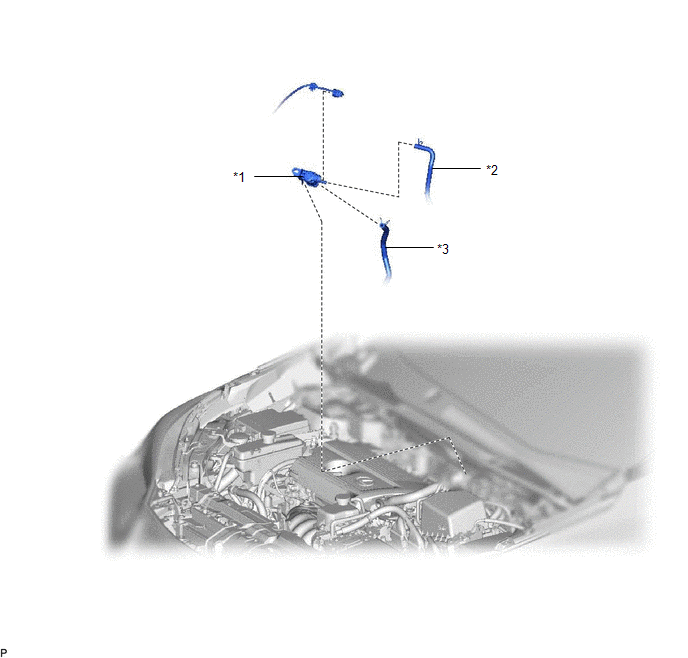
| *1 | PURGE VSV | *2 | FUEL VAPOR FEED HOSE |
| *3 | NO. 2 FUEL VAPOR FEED HOSE | - | - |
Removal
REMOVAL
PROCEDURE
1. REMOVE PURGE VSV
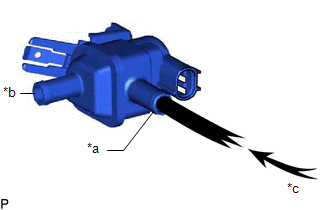
| (a) Disconnect the wire harness clamp and connector from the purge VSV. |
|
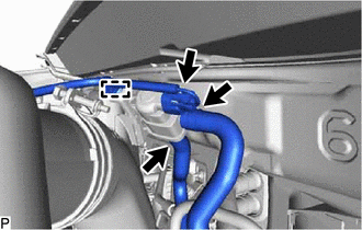
(b) Slide the 2 clamps and disconnect the fuel vapor feed hose and No. 2 fuel vapor feed hose from the purge VSV.
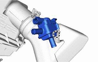
| (c) Detach the claw and remove the purge VSV from the air cleaner hose. |
|
Inspection
INSPECTION
PROCEDURE
1. INSPECT PURGE VSV
(a) Measure the resistance.
(1) Measure the resistance according to the value(s) in the table below.
Standard Resistance:
| Tester Connection | Condition | Specified Condition |
|---|---|---|
| 1 - 2 | 20°C | 23 to 26 Ω |
HINT:
If the result is not as specified, replace the purge VSV.
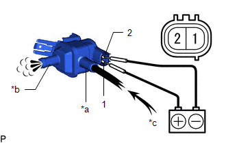
(b) Check the operation of the purge VSV.
| (1) Check that air does not flow from port F when air is applied to port E. |
|
| (2) Apply battery voltage between the terminals of purge VSV, and check the purge VSV operation. OK:
HINT: If the result is not as specified, replace the purge VSV. |
|
Installation
INSTALLATION
PROCEDURE
1. INSTALL PURGE VSV
(a) Install the purge VSV to the air cleaner hose with the claw.
(b) Connect the fuel vapor feed hose and No. 2 fuel vapor feed hose to the purge VSV and slide the 2 clamps to secure the hose.
(c) Connect the wire harness clamp and connector to the purge VSV.
READ NEXT:
 Components
COMPONENTS ILLUSTRATION *1 AIR FUEL RATIO SENSOR *2 INVERTER RESERVE TANK ASSEMBLY *3 NO. 1 EXHAUST MANIFOLD HEAT INSULATOR *4 WIRE HARNESS *5 RADIATOR HOSE CLAMP - -
SEE MORE:
Problem Symptoms Table
PROBLEM SYMPTOMS TABLE NOTICE: If the main body ECU (multiplex network body ECU) is replaced, refer to the Smart Access System with Push-button Start (for Entry Function). Click here HINT:
Use the table below to help determine the cause of problem symptoms. If multiple suspected areas are list
Diagnostic Trouble Code Chart
DIAGNOSTIC TROUBLE CODE CHART Blind Spot Monitor System DTC No. Detection Item Note Link C1A45 Vehicle Speed Sensor - C1A46 Yaw Rate Sensor - C1A47 Steering Angle Sensor - C1AB0 Short to +B in Outer Mirror Indicator(Master) - C1AB1 S
