Lexus NX: A/C Inverter Cooling / Heating System Malfunction (B1475)
DESCRIPTION
The temperature sensor of the compressor with motor assembly detects the A/C inverter temperature.
If the temperature exceeds the maximum, operation of the compressor with motor assembly will be stopped, and this DTC will be stored.
| DTC No. | Detection Item | DTC Detection Condition | Trouble Area | Memory | Note |
|---|---|---|---|---|---|
| B1475 | A/C Inverter Cooling / Heating System Malfunction | Temperature of the A/C inverter is outside the specified range (temperature is too high), or there is an open or short to ground in the temperature sensor circuit |
| Memorized | - |
CAUTION / NOTICE / HINT
CAUTION:
- Wear insulated gloves and pull out the service plug grip before inspection as procedures may require disconnecting high-voltage connectors. Carry the removed service plug in your pocket to prevent other technicians from accidentally reconnecting it while you are servicing the vehicle.
- Do not touch the high-voltage connectors or terminals for 10 minutes after the service plug grip is removed.
NOTICE:
-
After the power switch is turned off, there may be a waiting time before disconnecting the negative (-) auxiliary battery terminal.
Click here
.gif)
-
When disconnecting and reconnecting the auxiliary battery terminal
Click here
HINT:
When disconnecting and reconnecting the auxiliary battery, there is an automatic learning function that completes learning when the respective system is used.
Click here
- The hybrid control system and air conditioning system output DTCs separately. Perform troubleshooting for the hybrid control system first if DTCs from these systems are output simultaneously.
PROCEDURE
| 1. | CHECK CAN COMMUNICATION SYSTEM |
(a) Using the Techstream, check if the CAN communication system is functioning normally.
Click here
| Result | Proceed to |
|---|---|
| CAN communication system DTCs are not output | A |
| CAN communication system DTCs are output | B |
| B | .gif) | GO TO CAN COMMUNICATION SYSTEM |
|
.gif)
| 2. | PERFORM ACTIVE TEST USING TECHSTREAM |
(a) Connect the Techstream to the DLC3.
(b) Turn the power switch on (IG).
(c) Turn the Techstream on.
(d) Enter the following menus: Powertrain / Engine and ECT / Active Test.
(e) Check the operation by referring to the table below.
Powertrain > Engine and ECT > Active Test| Tester Display | Measurement Item | Control Range | Diagnostic Note |
|---|---|---|---|
| Control the Electric Cooling Fan | Control electric cooling fan motor | ON/OFF | Perform this test when the following conditions are met:
|
| Tester Display |
|---|
| Control the Electric Cooling Fan |
OK:
Electric cooling fan operates smoothly.
| NG | | GO TO COOLING FAN SYSTEM |
|
| 3. | CHECK REFRIGERANT PRESSURE |
(a) Install a manifold gauge set.
Click here
(b) Turn the power switch on (READY).
| (c) Read the manifold gauge pressure when the following conditions are met. (1) Prepare the vehicle according to the table below.
|
|
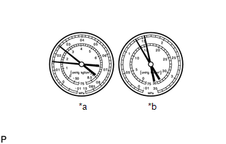
Standard Pressure:
Low pressure side
150 to 250 kPa (1.5 to 2.5 kgf/cm2, 22 to 36 psi)
High pressure side
1370 to 1570 kPa (14 to 16 kgf/cm2, 199 to 228 psi)
| NG | | CHARGE REFRIGERANT |
|
| 4. | CHECK FOR DTC |
(a) Clear the DTCs.
Click here
(b) Turn the power switch on (READY).
(c) Prepare the vehicle according to the table below.
| Item | Condition |
|---|---|
| Blower speed | HI |
| A/C switch | On |
| Temperature setting | MAX. COLD |
(d) Check for DTCs.
Click here
| Result | Proceed to |
|---|---|
| DTC B1475 is not output | A |
| DTC B1475 is output | B |
NOTICE:
If the engine keeps idling when ambient temperature is high, the compressor with motor assembly may automatically stop to protect the inverter circuit, and DTC B1475 may be stored.
| A | | USE SIMULATION METHOD TO CHECK |
| B | | REPLACE COMPRESSOR WITH MOTOR ASSEMBLY |
READ NEXT:
 A/C Inverter Load System Malfunction (B1476)
DESCRIPTION The operation of the compressor with motor assembly is stopped and this DTC is stored if the rotation load is too large or too small while the compressor with motor assembly is operating.
A/C Inverter Low Voltage Power Resource System Malfunction (B1477)
DESCRIPTION The compressor with motor assembly monitors the inverter control power voltage in the circuit. The hybrid vehicle control ECU stops the compressor control and stores this DTC when the moni
Communication Malfunction (Bus Ic) (B1497)
DESCRIPTION The air conditioning harness assembly connects the air conditioning amplifier assembly and the servo motors. The air conditioning amplifier assembly supplies power and sends operation inst
SEE MORE:
Precaution
PRECAUTION PRECAUTION FOR DISCONNECTING CABLE FROM NEGATIVE AUXILIARY BATTERY TERMINAL NOTICE: After the power switch is turned off, the radio receiver assembly records various types of memory and settings. As a result, after turning the power switch off, be sure to wait for the time specified in th
Installation
INSTALLATION CAUTION / NOTICE / HINT CAUTION: Wear protective gloves. Sharp areas on the parts may injure your hands. HINT:
Use the same procedure for the RH and LH sides.
The procedure listed below is for the LH side.
PROCEDURE 1. INSTALL FRONT SEAT ASSEMBLY LH (a) Place the front seat asse
