Lexus NX: All Doors LOCK/UNLOCK Functions do not Operate Via Door Control Switch
DESCRIPTION
The main body ECU (multiplex network body ECU) receives switch signals from the door control switch assembly on the front passenger door and activates the door lock motor on each door according to these signals.
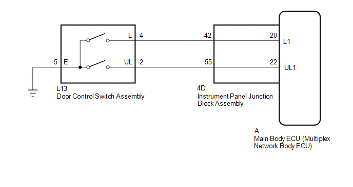
WIRING DIAGRAM
CAUTION / NOTICE / HINT
NOTICE:
- When using the Techstream with the vehicle power switch off, connect the Techstream to the DLC3 and turn a courtesy light switch on and off at intervals of 1.5 seconds or less until communication between the Techstream and the vehicle begins. Then select Model Code "KEY REGIST" under manual mode and enter the following menus: Body Electrical / Entry&Start(CAN). While using the Techstream, periodically turn a courtesy light switch on and off at intervals of 1.5 seconds or less to maintain communication between the Techstream and the vehicle.
-
If the main body ECU (multiplex network body ECU) is replaced, refer to the Smart Access System with Push-button Start (for Entry Function).
Click here
.gif)
PROCEDURE
| 1. | READ VALUE USING TECHSTREAM (Door Lock SW-Lock, Door Lock SW-Unlock) |
(a) Connect the Techstream to the DLC3.
(b) Turn the power switch on (IG).
(c) Turn the Techstream on.
(d) Enter the following menus: Body Electrical / Main Body / Data List.
(e) Read the Data List according to the display on the Techstream.
Body Electrical > Main Body > Data List| Tester Display | Measurement Item | Range | Normal Condition | Diagnostic Note |
|---|---|---|---|---|
| Door Lock SW-Lock | Door control switch assembly lock signal | OFF or ON | OFF: Lock side of door control switch assembly not pushed ON: Lock side of door control switch assembly pushed | - |
| Door Lock SW-Unlock | Door control switch assembly unlock signal | OFF or ON | OFF: Unlock side of door control switch assembly not pushed ON: Unlock side of door control switch assembly pushed | - |
| Tester Display |
|---|
| Door Lock SW-Lock |
| Door Lock SW-Unlock |
OK:
The Techstream indicates ON or OFF according to the switch operation shown in the table.
| OK | .gif) | REPLACE MAIN BODY ECU (MULTIPLEX NETWORK BODY ECU) |
|
.gif)
| 2. | INSPECT DOOR CONTROL SWITCH ASSEMBLY |
(a) Remove the door control switch assembly.
Click here
(b) Inspect the door control switch assembly.
Click here
| NG | | REPLACE DOOR CONTROL SWITCH ASSEMBLY |
|
| 3. | CHECK HARNESS AND CONNECTOR (DOOR CONTROL SWITCH ASSEMBLY - INSTRUMENT PANEL JUNCTION BLOCK ASSEMBLY AND BODY GROUND) |
(a) Disconnect the L13 door control switch assembly connector.
(b) Disconnect the 4D instrument panel junction block assembly connector.
(c) Measure the resistance according to the value(s) in the table below.
Standard Resistance:
| Tester Connection | Condition | Specified Condition |
|---|---|---|
| L13-4 (L) - 4D-42 | Always | Below 1 Ω |
| L13-2 (UL) - 4D-55 | Always | Below 1 Ω |
| L13-5 (E) - Body ground | Always | Below 1 Ω |
| L13-4 (L) or 4D-42 - Body ground | Always | 10 kΩ or higher |
| L13-2 (UL) or 4D-55 - Body ground | Always | 10 kΩ or higher |
| NG | | REPAIR OR REPLACE HARNESS OR CONNECTOR |
|
| 4. | INSPECT INSTRUMENT PANEL JUNCTION BLOCK ASSEMBLY |
(a) Remove the instrument panel junction block assembly.
Click here
(b) Remove the main body ECU (multiplex network body ECU) from the instrument panel junction block assembly.
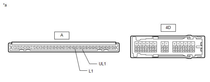
| *a | Component without harness connected (Instrument Panel Junction Block Assembly) | - | - |
(c) Measure the resistance according to the value(s) in the table below.
Standard Resistance:
| Tester Connection | Condition | Specified Condition |
|---|---|---|
| A-20 (L1) - 4D-42 | Always | Below 1 Ω |
| A-22 (UL1) - 4D-55 | Always | Below 1 Ω |
| OK | | REPLACE MAIN BODY ECU (MULTIPLEX NETWORK BODY ECU) |
| NG | | REPLACE INSTRUMENT PANEL JUNCTION BLOCK ASSEMBLY |
READ NEXT:
 Only Back Door cannot be Opened
DESCRIPTION The main body ECU (multiplex network body ECU) receives signals from the back door opener switch assembly. Then, the main body ECU (multiplex network body ECU) activates the back door lock
Components
COMPONENTS ILLUSTRATION *1 DECK FLOOR BOX LH *2 NO. 3 DECK BOARD SUB-ASSEMBLY *3 REAR DECK FLOOR BOX *4 NEGATIVE AUXILIARY BATTERY TERMINAL N*m (kgf*cm, ft.*lbf): Specified
SEE MORE:
All Door Entry Lock/Unlock Functions do not Operate, but Wireless Functions Operate
DESCRIPTION When the wireless operation can be used to lock and unlock the doors, communication between the door control receiver and certification ECU (smart key ECU assembly) is normal. If the entry lock and unlock functions do not operate, the entry cancel function may be set through the customiz
Transmission Control Switch Circuit
DESCRIPTION When the shift lever is in S, different ranges can be chosen using the floor shift sequential gate. WIRING DIAGRAM PROCEDURE 1. READ VALUE USING TECHSTREAM (SPORTS MODE) (a) Connect the Techstream to the DLC3. (b) Turn the power switch on (IG). (c) Enter the following menus: Po
